Supercharge Your Innovation With Domain-Expert AI Agents!

Positioning mapping method and system based on UWB and visual SLAM fusion algorithm

A fusion algorithm and vision technology, applied in the direction of location information-based services, navigation, instruments, etc., can solve problems affecting positioning accuracy and achieve the effect of reducing cumulative location errors

Active Publication Date: 2022-04-01
TSINGHUA UNIV
View PDF8 Cites 1 Cited by
  • Summary
  • Abstract
  • Description
  • Claims
  • Application Information

AI Technical Summary

Problems solved by technology

[0003] Visual positioning uses the camera to obtain surrounding images to obtain environmental information, and the selection of key frames will also affect the positioning accuracy

Method used


Image

  • Positioning mapping method and system based on UWB and visual SLAM fusion algorithm
  • Positioning mapping method and system based on UWB and visual SLAM fusion algorithm
  • Positioning mapping method and system based on UWB and visual SLAM fusion algorithm

Examples


Embodiment 1

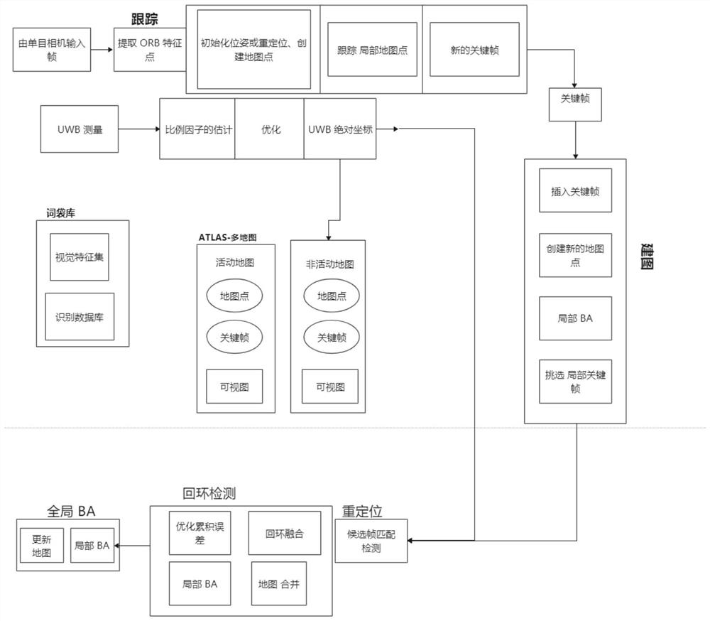
[0048] Such as figure 1 As shown, Embodiment 1 of the present invention proposes a positioning and mapping method for UWB and camera sensor fusion, the method includes the following steps:

[0049]1. Take the initial position of the mobile robot as the origin, and the initial orientation as the X coordinate axis to establish a world coordinate system. The UWB positioning tag is located at the origin of the body frame, which is the center of gravity of the rear axle, and other UWB positioning anchors are on the ground. During the movement of the mobile robot, by obtaining the UWB signal transmitted by the UWB positioning tag and the UWB positioning anchor point in real time, the classic MDS algorithm (Multiple Dimensional Scalling, dimensionality reduction algorithm) is used to initialize the first UWB position, and the EKF algorithm (Extended Kalman Filter, extended Kalman filter) to update and obtain UWB coordinates. During the operation of the trolley, the camera runs in re...

Embodiment 2

[0085] Embodiment 2 of the present invention proposes a positioning and mapping system based on the fusion algorithm of UWB and visual SLAM, which is implemented based on the method of Embodiment 1. The system includes: an acquisition module, a key frame extraction module, a coordinate system conversion module, and detection and mapping module; among them,

[0086] The acquisition module is used to obtain the UWB signal transmitted by the UWB positioning tag and the UWB positioning anchor point in real time, obtain the coordinates of the moving vehicle in the UWB coordinate system, acquire the image containing the environmental information collected by the camera synchronously, and establish the camera coordinate system;

[0087] The key frame extraction module is used to process the image containing the environment information, calculate the inter-frame motion according to the feature point matching between the frames, extract the feature point, and select the image satisfying...


PUM


Abstract

The invention discloses a UWB and visual SLAM fusion algorithm-based positioning mapping method and system, and the method comprises the steps: obtaining a UWB signal transmitted by a UWB positioning tag and a UWB positioning anchor point in real time, obtaining the coordinates of a moving vehicle in a UWB coordinate system, synchronously obtaining an image collected by a camera, and building a camera coordinate system; processing the image, and selecting the image meeting the condition as a key frame according to inter-frame feature point matching, inter-frame motion calculation and feature point extraction; unifying a camera coordinate system and a UWB coordinate system according to a track matching method; the key frame is converted into absolute coordinates with a UWB coordinate system, closed-loop detection is carried out, whether the key frame is tracked or not is judged, if not, map points are established according to the key frame, the established map is put into a map set to be stored, and map fusion is carried out on the newly-put map and the common part of the sub-map in the map set; and if yes, searching a matching map meeting the current position information in the map set.

Description

technical field [0001] The invention relates to the field of mobile robot positioning and mapping, in particular to a positioning and mapping method and system for UWB and visual SLAM fusion algorithms. Background technique [0002] In recent years, vision-based localization methods (such as visual odometry VO and simultaneous localization and mapping VSLAM) have become one of the key and difficult points in the research of mobile robotics. Visual SLAM explores unknown areas through cameras and builds maps that match the current environment without prior information. [0003] Visual positioning uses the camera to obtain surrounding images to obtain environmental information, and the selection of key frames will also affect the positioning accuracy. Moreover, during the running process, due to the structure of the camera sensor itself, in some dimly lit places, there will be too few or no feature points extracted, resulting in tracking failures, or abnormal perception due to...

Claims


Application Information

Patent Timeline
IPC IPC(8): G01C21/00G01C21/36H04W4/02
Inventor 张新钰苑婧郭世纯高国柱吴新刚
Owner TSINGHUA UNIV
Features
  • R&D
  • Intellectual Property
  • Life Sciences
  • Materials
  • Tech Scout
  • Unparalleled Data Quality
  • Higher Quality Content
  • 60% Fewer Hallucinations
Learn More