
Hall sensor-magnet geometry for large stroke linear position sensing

A stroke and magnet technology, applied in the field of position sensing unit, can solve problems such as the inability to support the control of the lens stroke

Pending Publication Date: 2022-04-01
COREPHOTONICS
View PDF0 Cites 0 Cited by
  • Summary
  • Abstract
  • Description
  • Claims
  • Application Information

AI Technical Summary

Problems solved by technology

Position sensing units currently used in the compact camera industry cannot support control of such a large lens travel

Method used


Image

  • Hall sensor-magnet geometry for large stroke linear position sensing
  • Hall sensor-magnet geometry for large stroke linear position sensing
  • Hall sensor-magnet geometry for large stroke linear position sensing

Examples


Embodiment Construction

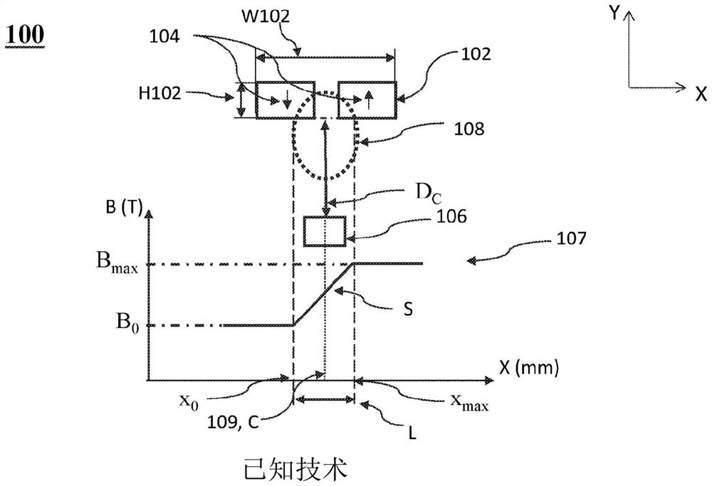
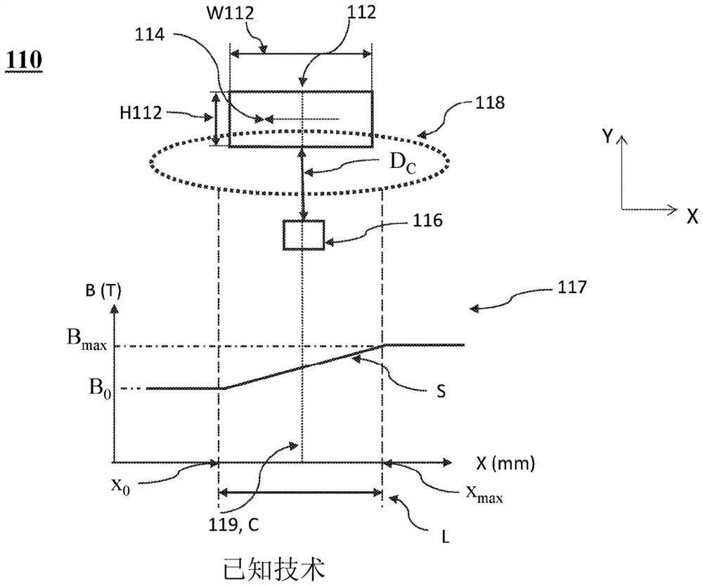
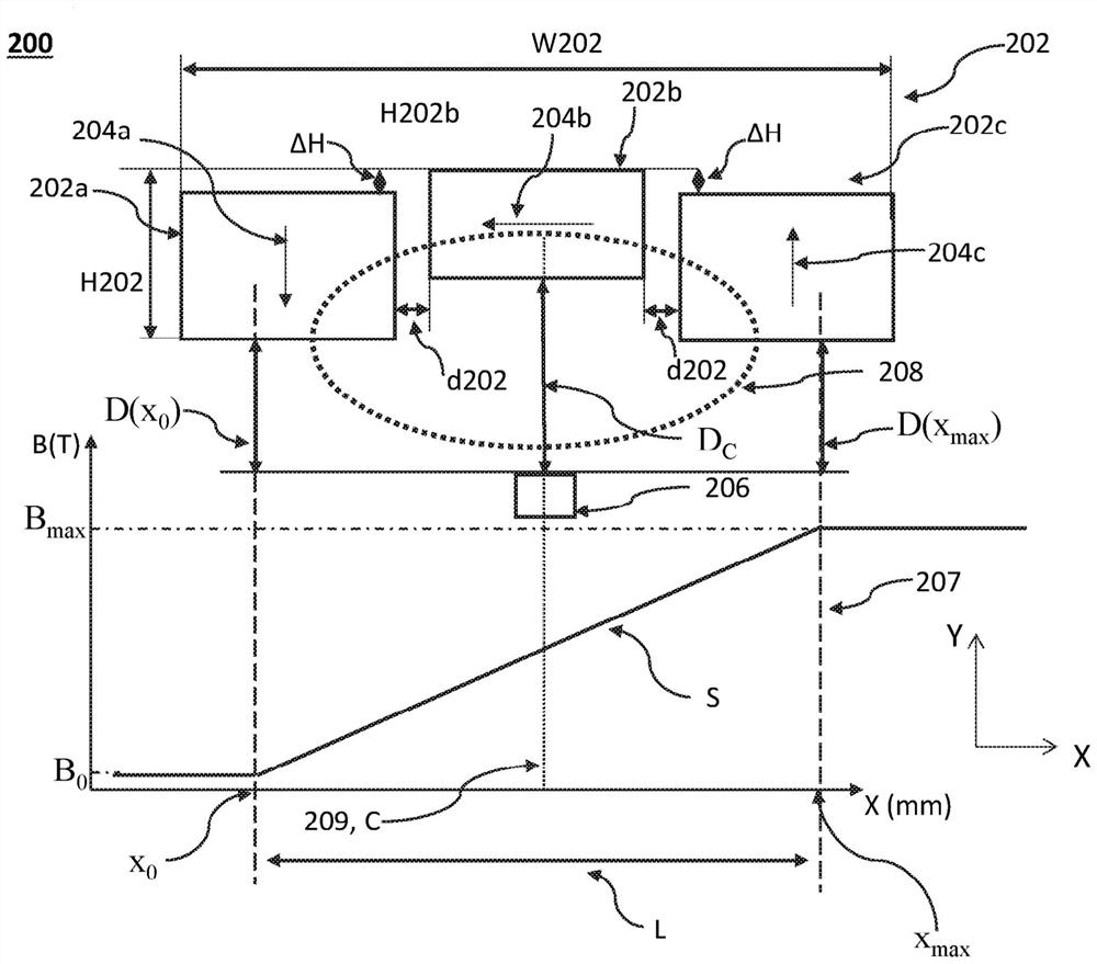
[0036] Figure 2A An embodiment of a position sensing unit disclosed herein and generally designated 200 including a magnetic assembly 202 and a magnetic flux measuring device 206 is shown. Graph 207 shows B versus the x-position of magnetic assembly 102 as measured by magnetic flux measurement device 106 . Figure 2B A magnetic field distribution 210 of the magnetic assembly 202 is shown. Box 212 represents the y position within the run L, where as Figure 2C A magnetic flux density 214 is shown as sensed by the magnetic flux measurement device 206 .

[0037] Magnetic assembly 202 includes three rectangular permanent magnets 202a, 202b, and 202c having respective magnetic polarizations 204a, 204b, and 204c. Magnets 202a and 202c are identical in shape and size, but have opposite magnetizations 204a and 204c, respectively. Magnets 202a and 202c are positioned symmetrically with respect to magnet 202b, i.e. magnets 202a and 202c are both (i) located at the same distance d20...


PUM


Abstract

Position sensing units comprising: a magnetic assembly (MA) having a width W measured in a first direction and a height H measured in a second direction, and comprising at least three magnets having respective magnetic polarizations defining at least one left MA domain, one middle MA domain and one right MA domain in the first direction, wherein the magnetic polarizations of each MA domain are different; and a magnetic flux measurement device (MFMD) for measuring a magnetic flux B, in which the MA moves relative to the MFMD in the first direction within a stroke L satisfying 1 mm < = L < = 100 mm, the stroke L starting at a first point x0, ending at an end point xmax, and a second point x0, ending at an end point xmax, and wherein a minimum value Dmin of an orthogonal distance D measured along the second direction between a specific MA domain and the MFMD satisfies L / Dmingt; 10.

Description

[0001] Related applications [0002] This application claims priority to U.S. Provisional Patent Application Serial No. 63 / 059,200, filed July 31, 2020, the entire contents of which are incorporated herein by reference. technical field [0003] Embodiments disclosed herein relate generally to position sensing units, and more particularly to position sensing in compact digital cameras included within mobile electronic devices. Background technique [0004] Many compact digital cameras integrated into handheld electronic devices ("devices") such as smartphones or tablets use actuators such as voice coil motors (VCM) or stepper motors, For example: for driving a camera lens along a trajectory with a specific direction and extent ("travel" or "L"). The drive is controlled by a position sensing unit, usually based on a magnet assembly ("MA") relative to a magnetic flux measuring device (magnetic flux measuring device, MFMD) movement, the magnetic flux measuring device is, for ...

Claims


Application Information

Patent Timeline
IPC IPC(8): G01D5/14G01R33/06G01B7/04
CPCG01D5/145G01R33/1292G01R33/0385G01R33/0005G01R33/072G01D2205/18G01R33/07G01R33/0094G01B7/003H04N23/54H04N23/55G03B17/12H02K11/215H02K41/0356G03B2205/0069
Inventor 耶夫塔·科瓦尔纳达夫·古林斯基塔尔·科曼以法莲·戈登堡
Owner COREPHOTONICS
Learn More