Supercharge Your Innovation With Domain-Expert AI Agents!

Machine tool spindle

A technology for machine tool spindles and headstocks, applied to metal processing machinery parts, maintenance and safety accessories, metal processing equipment, etc., can solve problems such as short service life, achieve good integrity, prolong service life, and wide applicability

Active Publication Date: 2022-04-05
浙江海德曼智能装备股份有限公司
View PDF7 Cites 0 Cited by
  • Summary
  • Abstract
  • Description
  • Claims
  • Application Information

AI Technical Summary

Problems solved by technology

[0005] The object of the present invention is to solve the above-mentioned problems in the prior art, and propose a machine tool spindle, which solves the problem of short service life

Method used


Image

  • Machine tool spindle
  • Machine tool spindle
  • Machine tool spindle

Examples


Embodiment 1

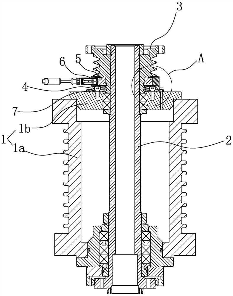
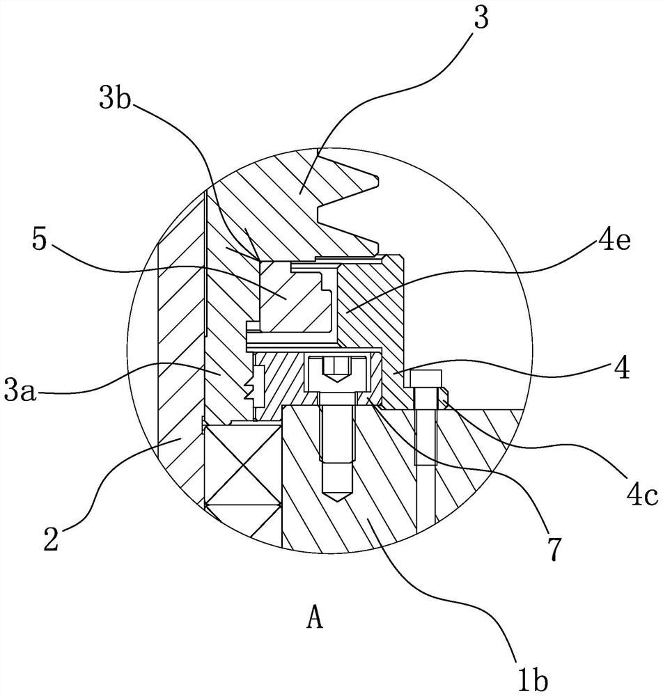
[0037] Such as figure 1 , figure 2 , image 3 , Figure 4 , Figure 5 , Image 6 , Figure 7A with Figure 7BAs shown, a machine tool spindle includes a spindle box 1, an encoder, a shaft body 2 with one end protruding from the spindle box 1, and a rotating member that is arranged on the shaft body 2 that extends out of the spindle box 1 and that is linked with the shaft body 2. 3. An installation seat 4 is fixed on the end surface of the spindle box 1 for the shaft body 2 to protrude from, and the encoder includes a reading member 6 and a magnet set on the shaft body 2 protruding from the spindle box 1 and inside the installation seat 4. Ring 5. Mounting seat 4 is ring-shaped and one end is close to rotating part 3 (here abutting against is not leaning against, that is, mounting seat is very close to rotating part but does not form contact), and the side of mounting seat 4 is provided with The matching groove 4a that runs through the radial direction, the matching gr...

Embodiment 2

[0042] The structure and principle of this embodiment are basically the same as that of Embodiment 1, the difference is that in this embodiment, the outer side of the reading member 6 near the front position has a ring-shaped installation part, and the installation part is attached to the matching groove 4a on the mounting base 4 around the notch.

Embodiment 3

[0044] The structure and principle of this embodiment are basically the same as that of Embodiment 1, the difference is that in this embodiment, the rotating part 3 is not provided with an extension part 3a, and the magnetic ring 5 is directly sleeved outside the shaft body 2 and connected to the rotating part 3 is fixed by fasteners.


PUM


Abstract

The invention provides a machine tool spindle, and belongs to the technical field of machine tools. The problem that the service life is short is solved. One end of the shaft body extends out of the spindle box, the rotating part is arranged on the shaft body extending out of the spindle box and is in linkage with the shaft body, a mounting seat is fixed on the spindle box, the encoder comprises a reading part and a magnetic ring arranged on the shaft body and located on the inner side of the mounting seat, the mounting seat is annular, one end of the mounting seat abuts against the rotating part, and the other end of the mounting seat abuts against the rotating part. A matching groove penetrating in the radial direction is formed in the side portion of the installation base, the front portion of the reading piece is fixedly embedded in the matching groove, and the length and the width of the matching groove are matched with the size of the side face of the front portion of the reading piece. The device has the advantages of long service life, wide applicability, compact structure and the like.

Description

technical field [0001] The invention belongs to the technical field of machine tools and relates to a machine tool spindle. Background technique [0002] An encoder is a device that compiles detection signals or data and converts them into signal forms that can be used for communication, transmission and storage. Divided by working principle, the encoder is divided into photoelectric type, magnetoelectric type and contact brush type, etc. Among them, the magnetic type encoder is widely used in various other encoders due to its simple structure, strong anti-interference, and fast response speed. For complex environments that cannot be applied, existing magnetoelectric encoders basically include a magnetic ring and a reading element (including a casing and an inductive element arranged in the casing, the inductive element can be a pulse type counting board). [0003] At present, magnetoelectric encoders are widely used in CNC machine tools. For example, the Chinese patent app...

Claims


Application Information

Patent Timeline
IPC IPC(8): B23B19/02B23Q11/00
Inventor 李陈亮汪助田海瑞韩照卫星
Owner 浙江海德曼智能装备股份有限公司
Features
  • R&D
  • Intellectual Property
  • Life Sciences
  • Materials
  • Tech Scout
  • Unparalleled Data Quality
  • Higher Quality Content
  • 60% Fewer Hallucinations
Learn More