Rapid wall dividing device for building construction

A building construction and wall technology, which is applied in construction, building maintenance, building construction, etc., can solve the problems of cutting disc wear, reduce the service life of cutting discs, troubles, etc., and achieve the effect of accelerating promotion and realizing segmentation

Pending Publication Date: 2022-04-05
高振吉
View PDF9 Cites 1 Cited by
  • Summary
  • Abstract
  • Description
  • Claims
  • Application Information

AI Technical Summary

Problems solved by technology

[0002] When the house is being decorated, due to functional zoning and other reasons, the wall will be cut and opened. Of course, the load-bearing wall cannot be hollowed out or chiseled. When dividing the wall, the current traditional method is to use The combination of a small hammer and a sledgehammer can cut the wall. Of course, the cutting machine can also be used for cutting, but when the cutting machine is used for cutting, the friendship wall is relatively thick, and the cutting disc is severely worn during cutting. It will greatly reduce the service life of the cutting disc, and it is cumbersome to replace the cutting disc. With the improvement of the decoration requirements, the cutting of the wall is indispensable. Therefore, the inventor invented a building Construction wall quick split device to solve the problem of wall cutting

Method used


Image

  • Rapid wall dividing device for building construction
  • Rapid wall dividing device for building construction

Examples


Embodiment Construction

[0016] The following will clearly and completely describe the technical solutions in the embodiments of the present invention with reference to the accompanying drawings in the embodiments of the present invention. Obviously, the described embodiments are only some, not all, embodiments of the present invention. Based on the embodiments of the present invention, all other embodiments obtained by persons of ordinary skill in the art without making creative efforts belong to the protection scope of the present invention.

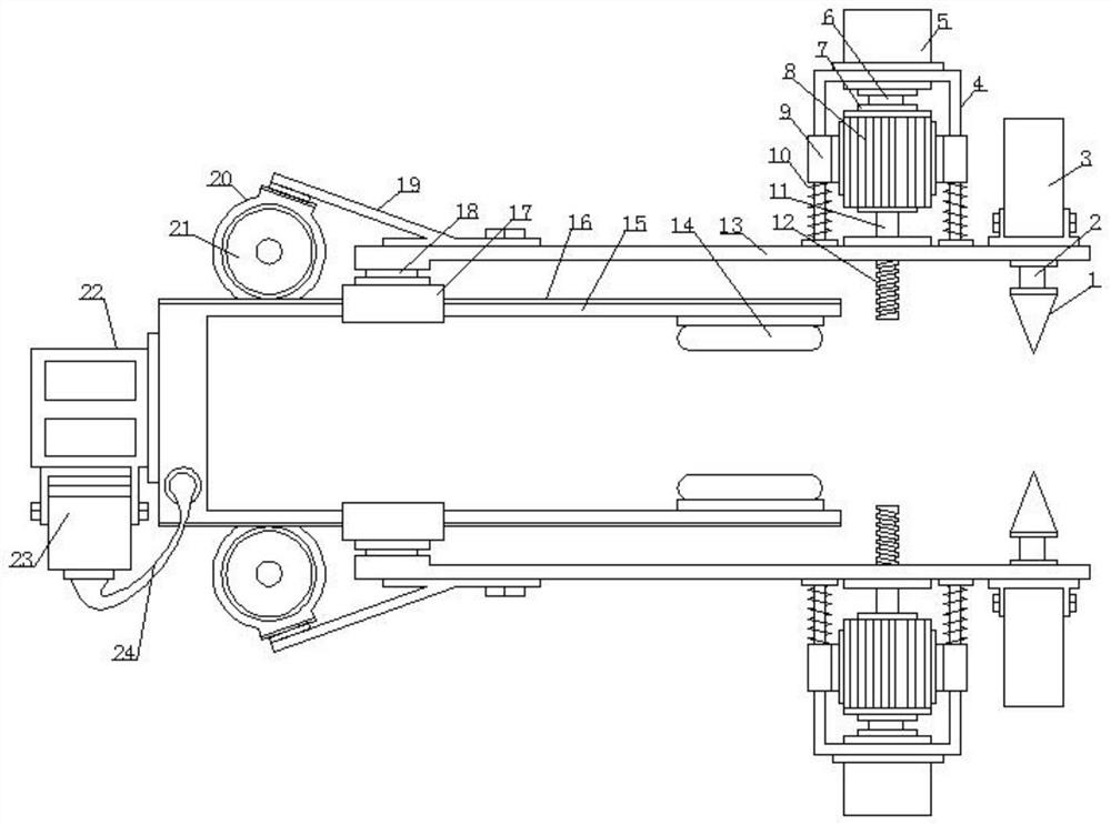
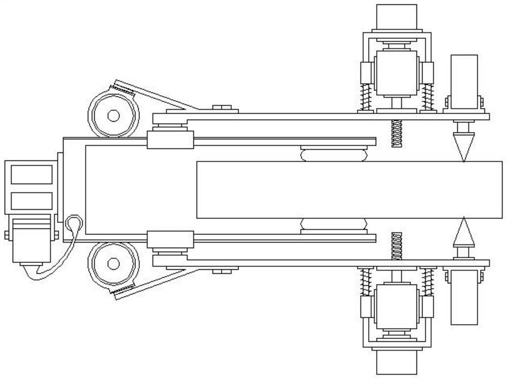
[0017] see Figure 1-2 , the present invention provides a technical solution:

[0018] A device for quickly dividing walls for building construction, comprising a sliding frame 15, sliding tubes 17 are symmetrically sleeved on both side walls of the sliding frame 15, and connecting rods 18 are welded on the outer surface of the sliding tubes 17, and the outer surface of the connecting rods 18 is The connecting plate 13 is welded at the end, and the left side ...


PUM


Abstract

The invention aims to solve the problem of wall cutting, and discloses a rapid wall cutting device for building construction, which comprises a sliding frame, two side walls of the sliding frame are symmetrically sleeved with sliding pipes, connecting rods are welded to the outer surfaces of the sliding pipes, connecting plates are welded to the outer ends of the connecting rods, inclined frames are fixedly mounted on the left sides of the outer surfaces of the connecting plates, and the inclined frames are fixedly mounted on the left sides of the outer surfaces of the connecting plates. A second motor is fixedly mounted at the left end of the inclined frame, a gear is mounted in the middle of the second motor, a first hydraulic cylinder is fixedly mounted at the right end of the outer side face of the connecting plate, a first piston rod is mounted in the middle of the first hydraulic cylinder, a conical block is fixedly mounted at the end of the first piston rod, and a guide frame is fixedly mounted on the outer surface of the connecting plate. And a second hydraulic cylinder is fixedly mounted at the top end of the guide frame. Through the arrangement of the conical block and the drill rod, drilling treatment can be effectively carried out on a wall body, help is provided for wall body segmentation, pushing of the wall body can be accelerated through expansion of the air bag, and wall body segmentation is achieved.

Description

technical field [0001] The invention relates to the construction field, in particular to a rapid wall dividing device for building construction. Background technique [0002] When the house is being decorated, due to functional zoning and other reasons, the wall will be cut and opened. Of course, the load-bearing wall cannot be hollowed out or chiseled. When dividing the wall, the current traditional method is to use The combination of a small hammer and a sledgehammer can cut the wall. Of course, the cutting machine can also be used for cutting, but when the cutting machine is used for cutting, the friendship wall is relatively thick, and the cutting disc is severely worn during cutting. It will greatly reduce the service life of the cutting disc, and it is cumbersome to replace the cutting disc. With the improvement of the decoration requirements, the cutting of the wall is indispensable. Therefore, the inventor invented a building The wall quick split device is used for ...

Claims


Application Information

Patent Timeline
Patent Type & Authority Applications(China)
IPC IPC(8): B28D1/14B28D7/00E04G23/02
Inventor 高振吉
Owner 高振吉
Why Eureka
Try Eureka