
One-time mechanical turn-up boosting capsule drum

A capsule and mechanical technology, applied in the field of mold structure, can solve the problems of uneven turn-up force, high energy consumption, and many bubbles, and achieve the effects of uniform sidewall turn-up height, accurate material distribution and uniform turn-up force.

Pending Publication Date: 2022-04-05
JIEYANG TIANYANG MOLD
View PDF3 Cites 0 Cited by
  • Summary
  • Abstract
  • Description
  • Claims
  • Application Information

AI Technical Summary

Problems solved by technology

In the current all-steel radial tire building drum, there are existing mechanical turn-up forming drums, such as "a mechanical forming drum" (patent No. 01269962.4), "conical oblique wedge slider type building drum" (patent No. 200320110467.9), "A tire metal forming drum" (Patent No. 200320103041.0)", etc., there are discontinuities on the turn-up circumference, uneven turn-up force, deep indentation, inaccurate material distribution position, inconsistent height of sidewall turn-up, and many bubbles , Difficult to adjust during work, poor stability, complex structure, high price, heavy weight, high energy consumption, etc.; The package is not in place, the quality of the turn-up is unstable, the pass rate of the dynamic balance test is low, and the labor intensity is high, and the production efficiency is low; therefore, it is necessary to provide a new type of all-steel radial tire turn-up forming drum with better performance.

Method used


Image

  • One-time mechanical turn-up boosting capsule drum
  • One-time mechanical turn-up boosting capsule drum
  • One-time mechanical turn-up boosting capsule drum

Examples


Embodiment 1

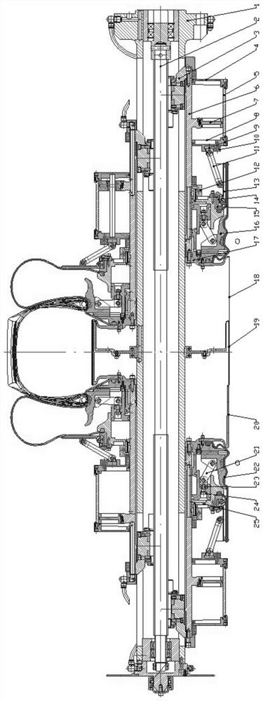
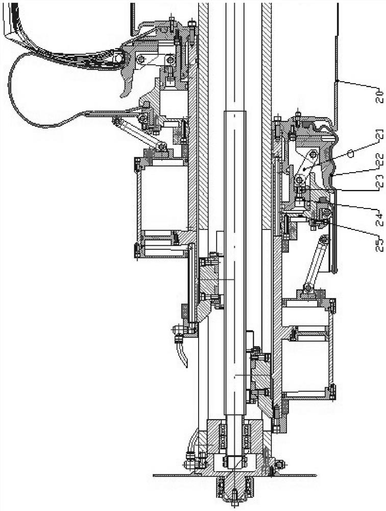
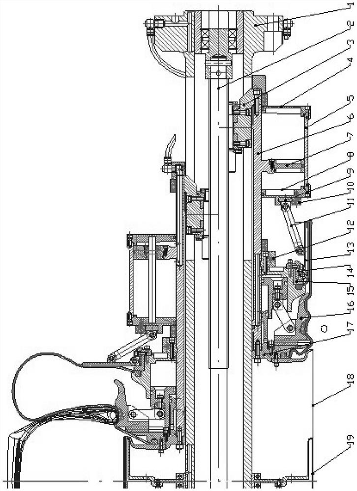
[0021] As shown in the figure: the supply includes main shaft 1, ball screw 2, transmission key 3, right cylinder head 4, cylinder body 5, side bushing 6, piston 7, left cylinder head 8, connecting rod seat C9, four petals Ring 10, large connecting rod 11, fixed ring 12, booster plate 13, connecting rod seat B14, capsule pressure ring 15, sector block 16, sector plate 17, outer ring 18, center ring 19, inner ring 20, small connecting rod 21, reverse package capsule 22, connecting rod seat A23, movable ring 24, cylinder body A25.

[0022] Preferably, the left cylinder head 8, the right cylinder head 4, and the cylinder block 5 constitute a double-acting cylinder, which is slidingly connected to the side bushing 6; the piston 7 is fixed on the side bushing 6; the One end of the large connecting rod 11 is connected to the connecting rod seat C9, and is fixed on the left cylinder head 8 through the four-petal ring 10, and the other end of the large connecting rod 11 is connected w...

Embodiment 2

[0024] As shown in the figure: the supply includes main shaft 1, ball screw 2, transmission key 3, right cylinder head 4, cylinder body 5, side bushing 6, piston 7, left cylinder head 8, connecting rod seat C9, four petals Ring 10, large connecting rod 11, fixed ring 12, booster plate 13, connecting rod seat B14, capsule pressure ring 15, sector block 16, sector plate 17, outer ring 18, center ring 19, inner ring 20, small connecting rod 21, reverse package capsule 22, connecting rod seat A23, movable ring 24, cylinder body A25.

[0025] Preferably, the left cylinder head 8, the right cylinder head 4, and the cylinder block 5 constitute a double-acting cylinder, which is slidingly connected to the side bushing 6; the piston 7 is fixed on the side bushing 6; the One end of the large connecting rod 11 is connected to the connecting rod seat C9, and is fixed on the left cylinder head 8 through the four-petal ring 10, and the other end of the large connecting rod 11 is connected w...

Embodiment 3

[0027] As shown in the figure: the supply includes main shaft 1, ball screw 2, transmission key 3, right cylinder head 4, cylinder body 5, side bushing 6, piston 7, left cylinder head 8, connecting rod seat C9, four petals Ring 10, large connecting rod 11, fixed ring 12, booster plate 13, connecting rod seat B14, capsule pressure ring 15, sector block 16, sector plate 17, outer ring 18, center ring 19, inner ring 20, small connecting rod 21, reverse package capsule 22, connecting rod seat A23, movable ring 24, cylinder body A25.

[0028] Preferably, the left cylinder head 8, the right cylinder head 4, and the cylinder block 5 constitute a double-acting cylinder, which is slidingly connected to the side bushing 6; the piston 7 is fixed on the side bushing 6; the One end of the large connecting rod 11 is connected to the connecting rod seat C9, and is fixed on the left cylinder head 8 through the four-petal ring 10, and the other end of the large connecting rod 11 is connected w...


PUM


Abstract

The invention discloses a one-time mechanical reverse package boosting capsule drum which comprises a main shaft (1), a ball screw (2), a transmission key (3), a right cylinder cover (4), a cylinder body (5), a side shaft sleeve (6), a piston (7), a left cylinder cover (8), a connecting rod seat C (9), a four-valve ring (10), a large connecting rod (11), a fixing ring (12), a boosting plate (13), a connecting rod seat B (14) and a capsule pressing ring (15). The invention aims to overcome the defects in the prior art, and provides a one-time mechanical turn-up boosting capsule drum which is good in turn-up circumference continuity, uniform in turn-up force, shallow in indentation, accurate in material distribution position, consistent in sidewall turn-up height, free of bubble generation, easy to adjust in work, good in stability and high in reliability. And the device is simple in structure, low in cost, light in weight, low in energy consumption and high in production efficiency.

Description

technical field [0001] The present invention relates to the field of mold structures, in particular to a tire active mold required for vulcanization of radial tires of automobiles. Background technique [0002] The all-steel radial tire building drum is the executive mechanism of tire building, which affects the accuracy of the material distribution of each part of the formed tire blank, plays an extremely important role in the durability of the tire, and directly affects the tire building quality. In the current all-steel radial tire building drum, there are existing mechanical turn-up forming drums, such as "a mechanical forming drum" (patent No. 01269962.4), "conical oblique wedge slider type building drum" (patent No. 200320110467.9), "A tire metal forming drum" (Patent No. 200320103041.0)", etc., there are discontinuities on the turn-up circumference, uneven turn-up force, deep indentation, inaccurate material distribution position, inconsistent height of sidewall turn-...

Claims


Application Information

Patent Timeline
Patent Type & Authority Applications(China)
IPC IPC(8): B29D30/24B29D30/26
Inventor 吴贤开
Owner JIEYANG TIANYANG MOLD
Learn More