Walking type large-bearing combined steel pipe support and using method

A combination of steel pipes and walking technology, which is applied in the erection/assembly of bridges, bridges, buildings, etc., can solve the problems of low efficiency, low upper limit of support bearing capacity, low versatility and turnover, etc., to reduce labor and material waste, The effect of improving safety and bearing capacity, improving versatility and turnover rate

Pending Publication Date: 2022-04-05
山东高速尼罗投资发展有限公司
View PDF0 Cites 0 Cited by
  • Summary
  • Abstract
  • Description
  • Claims
  • Application Information

AI Technical Summary

Problems solved by technology

[0002] In the construction process of railway projects, a large number of cast-in-place concrete solid slab bridges need to be built, but the supports currently on the market, such as fastener-type scaffolding, bowl-buckle-type scaffolding, buckle-plate scaffolding, and portal-type scaffolding, are all light-weight brackets. This type of support has low load-bearing, high labor consumption and low erection safety, especially in the process of large-section roof concrete support, the upper limit of the bearing capacity of this type of support is low, and its installation and disassembly process is dangerous and cumbersome
Therefore, when pouring heavy-duty concrete, construction companies generally use on-site welded steel pipe brackets to achieve support, but this kind of steel pipe brackets are generally designed and manufactured according to the site conditions. Special brackets have irregular sizes and are universal Moreover, the tie rods on the steel pipe support are reinforced by on-site welding, which has a low safety factor and needs to be cut during disassembly, which will make the entire construction process cumbersome and dangerous, and the waste of materials is serious and the efficiency is low

Method used


Image

  • Walking type large-bearing combined steel pipe support and using method
  • Walking type large-bearing combined steel pipe support and using method
  • Walking type large-bearing combined steel pipe support and using method

Examples


Embodiment Construction

[0028] The technical solutions in the embodiments of the present invention will be clearly and completely described below with reference to the accompanying drawings in the embodiments of the present invention. Obviously, the described embodiments are only a part of the embodiments of the present invention, but not all of the embodiments. Based on the embodiments of the present invention, all other embodiments obtained by those of ordinary skill in the art without creative efforts shall fall within the protection scope of the present invention.

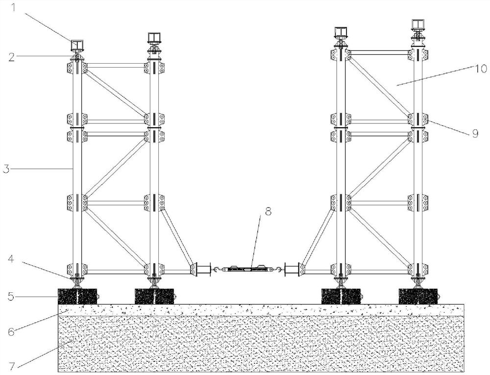
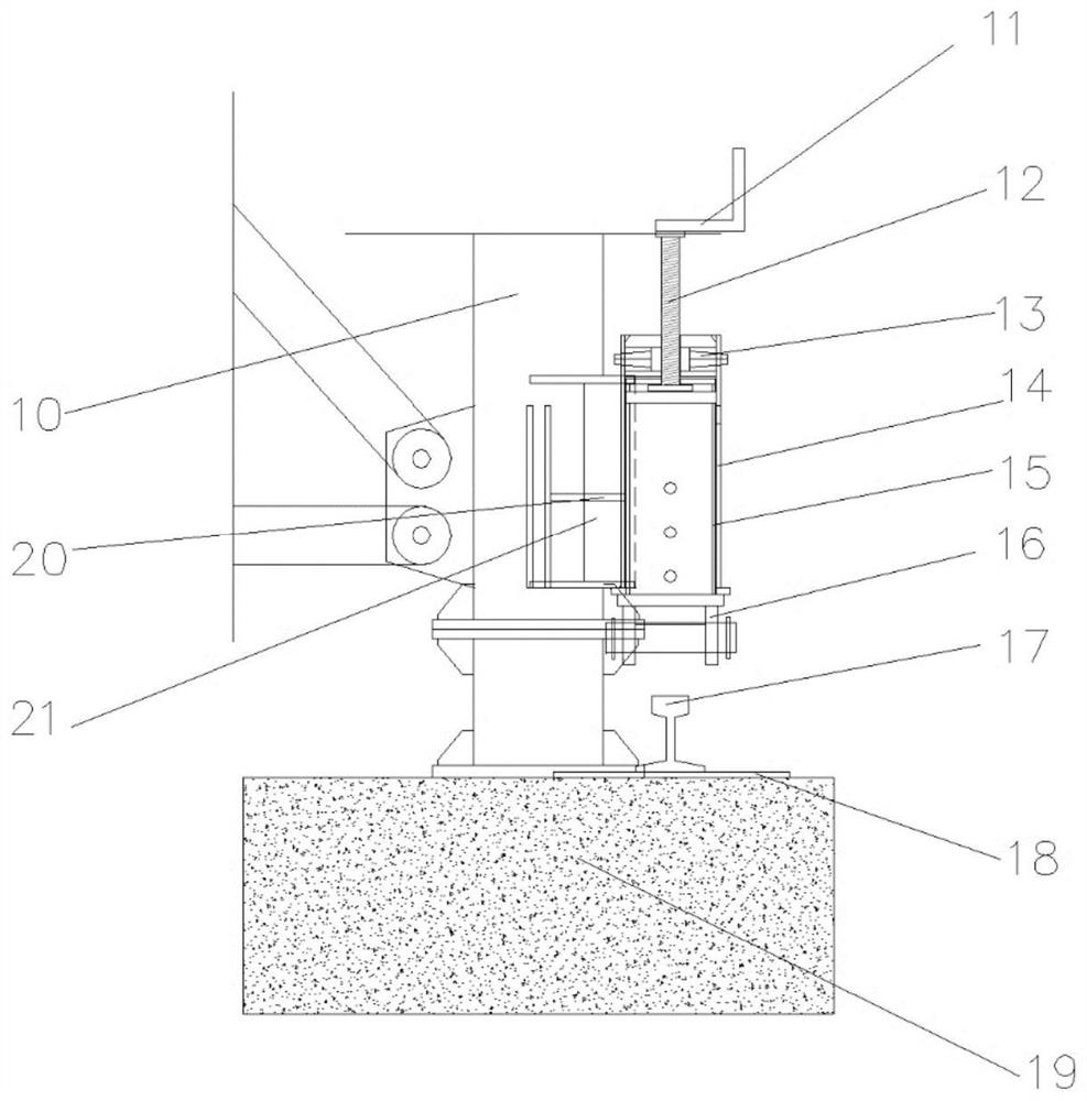
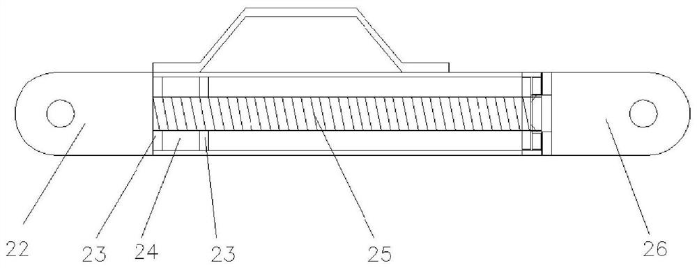
[0029] like Figure 1 to Figure 5 As shown, the present invention provides a walking type large load-bearing combined steel pipe support, which includes a sand and gravel cushion 19, and an anchor plate 5 is provided on the sand and gravel cushion 19, and the anchor plate 5 is laid in parallel with There are two steel rails 17 , and a lower fixed flask 4 is arranged in the middle of the two steel rails 17 , and the lower fixed flask 4...


PUM


Abstract

The invention provides a walking type large-bearing-capacity combined steel pipe support and a using method. The walking type large-bearing-capacity combined steel pipe support comprises a sand-gravel cushion layer and supporting stand columns, an anchoring plate is arranged on the sand-gravel cushion layer, two steel rails are laid on the anchoring plate in parallel, and a lower fixing sand box is arranged between the two steel rails; at least two supporting units are sequentially and detachably connected to the supporting stand column from top to bottom, and a sand box and a supporting beam are sequentially arranged at the upper end of the supporting unit located at the uppermost end of the supporting stand column from bottom to top; a fixing part is arranged on the lower portion of the supporting unit located at the lowermost end of the supporting stand column and can be connected with a lower fixing sand box. A walking assembly is fixedly connected to one side of the supporting unit at the lowermost end of the supporting stand column and can be in sliding connection with a steel rail. The device has the beneficial effects that flexibility and universality are achieved, the mounting and dismounting process is simple and rapid, meanwhile, overall dismounting can be conducted, labor and equipment consumption is reduced to the maximum extent, and efficiency is improved.

Description

technical field [0001] The invention belongs to the field of bridge engineering construction equipment, and in particular relates to a walking type large load-bearing combined steel pipe bracket and a using method. Background technique [0002] In the process of railway project construction, a large number of cast-in-place concrete solid slab bridges need to be built, but the brackets currently on the market, such as fastener-type scaffolding, bowl-type scaffolding, buckle-type scaffolding, portal scaffolding, etc., are all light-duty brackets. This kind of support has low bearing capacity, large labor consumption and low erection safety, especially in the process of large-section roof concrete support, the upper limit of the bearing capacity of this kind of support is low, and the installation and disassembly process is dangerous and cumbersome. Therefore, when pouring heavy-duty concrete, construction companies generally realize support by welding steel pipe brackets on si...

Claims


Application Information

Patent Timeline
Patent Type & Authority Applications(China)
IPC IPC(8): E01D21/00
Inventor 周凯歌
Owner 山东高速尼罗投资发展有限公司
Why Eureka
Try Eureka