Vehicle motor control system and method

A motor control and vehicle technology, which is applied to electrical components, emergency protection circuit devices, etc., can solve the problems of high cost, the main microcontroller cannot output PWM to control the motor, and the safety state of the electric drive system cannot be controlled. Good safety control effect, good safety effect

Pending Publication Date: 2022-04-05
HYCET TRANSMISSION TECH HEBEI CO LTD
View PDF7 Cites 0 Cited by
  • Summary
  • Abstract
  • Description
  • Claims
  • Application Information

AI Technical Summary

Problems solved by technology

[0006] The second method is to use the main microcontroller and the auxiliary microcontroller in series for gate drive logic control. In this form of control, when the main microcontroller fails, the auxiliary microcontroller (FPGA/CPLD) can control the gate drive logic. The drive system enters a safe state, but when the auxiliary microcontroller fails, the main microcontroller cannot output PWM to control the motor

Method used


Image

  • Vehicle motor control system and method
  • Vehicle motor control system and method
  • Vehicle motor control system and method

Examples


Embodiment 1

[0039] This embodiment relates to a vehicle motor control system, which mainly includes a controller, a latch and a gate drive circuit.

[0040] Wherein, the controller controls the normal operation of the motor through the enabling control of the gate drive circuit; the latch latches the safety state control signal according to the parameters during the normal operation of the motor; the gate drive circuit drives and connects the motor.

[0041]The gate drive circuit has a working state of controlling the normal operation of the motor under the enabling control of the controller, and when a failure of the controller occurs, the control signal enabling the control of the motor through a safe state The motor enters a safe state, and the safe state includes an ASC safe state when the motor runs at a high speed, and an SPO safe state when the motor runs at a low speed.

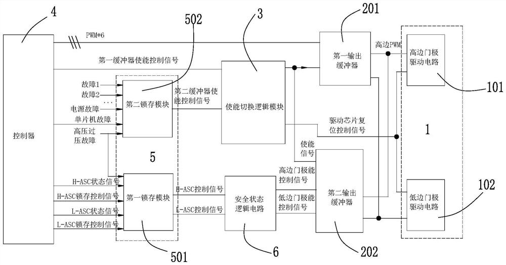
[0042] Based on the overall description above, figure 1 An exemplary structure of a vehicle motor control sy...

Embodiment 2

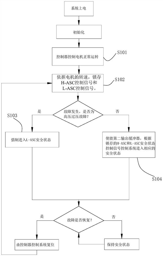
[0056] This embodiment relates to a vehicle motor control method, which generally includes the following steps:

[0057] The normal operation control step is to control the normal operation of the motor;

[0058] The latching step is to latch the safe state control signal according to the parameters during the normal operation of the motor;

[0059] The safety control step is to control the motor to enter a safe state with the latched safe state control signal when a control failure occurs in the motor, and the safe state includes the ASC safe state under the high speed operation of the motor, and the low speed of the motor SPO security state in operation.

[0060] Wherein, in the latching step, the latched security state control signal includes an ASC security state control signal.

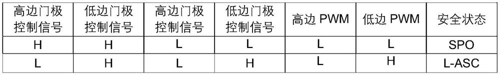
[0061] In order to achieve better control, the ASC security state control signal includes the L-ASC security state control signal and the H-ASC security state control signal. At the same time,...


PUM


Abstract

The invention provides a vehicle motor control method and device, and the method comprises a normal operation control step: controlling the normal operation of a motor; a latching step: latching a safety state control signal according to the parameters in the normal operation process of the motor; and a safety control step: when the motor has a control fault, the motor is controlled to enter a safety state by using a latched safety state control signal, and the safety state comprises an ASC safety state under high-speed operation of the motor and an SPO safety state under low-speed operation of the motor. Due to the fact that the latching step and the safety control step are matched, the safety state control signal is latched according to the parameters in the normal operation process of the motor, the motor is controlled to enter the safety state through the latched safety state control signal when the motor has a control fault, and the safety control effect is good.

Description

technical field [0001] The invention relates to the technical field of vehicle motor safety control, in particular to a vehicle motor control system; the invention also relates to a vehicle motor control method. Background technique [0002] With the increasing development and popularization of new energy vehicles, the functional safety of electric drive systems is particularly important. The motor controller itself must enter a safe state in the event of an emergency of its own failure, so as to ensure the safety of personnel and vehicles. Currently, the two most common active protection measures are SPO (Safty Pulse Off, also called Freewheeling) safety state and ASC (Active Short Circuit) safety state. The way to achieve the SPO safe state is to separate the motor from the controller by disconnecting all the switch tubes; the ASC safe state is to realize the separation of the motor and the controller by short-circuiting the upper bridge or the lower bridge. The form of ...

Claims


Application Information

Patent Timeline
IPC IPC(8): H02H7/09H02H7/093
Inventor 王伟王成刘浩杨超魏自家王振达周海龙曹明轩张孟孟
Owner HYCET TRANSMISSION TECH HEBEI CO LTD
Why Eureka
Try Eureka