Disconnecting link control system
A control system and knife switch technology, applied in information technology support systems, electrical components, emergency protection circuit devices, etc., can solve problems such as the inability to determine the correctness of the locking logic from the wiring, high requirements for maintenance personnel, and high probability of misoperation. It achieves the effect of facilitating troubleshooting, low level requirements, and stable and reliable logic
- Summary
- Abstract
- Description
- Claims
- Application Information
AI Technical Summary
Problems solved by technology
Method used
Image

Examples
Embodiment 1
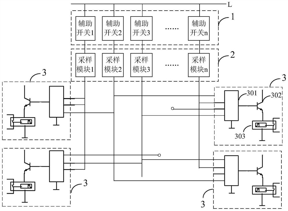
[0033] figure 1 The structural diagram of the knife switch control system provided by Embodiment 1 of the present invention, the knife switch control system of the embodiment of the present invention is used to control a plurality of knife switches in the bay on the bus, and the bay includes a knife switch with an auxiliary switch and circuit breakers, such as figure 1As shown, the knife gate control system includes an auxiliary switch 1, a sampling module 2, a control module 3 and a control loop.
[0034] The interval refers to the branch lines on the bus. The branch lines are equipped with isolation switches, grounding switches, circuit breakers, relays, etc. The switch has an obvious disconnection point, does not have an arc extinguishing device, and cannot be opened and closed under load. , the device that needs to be opened and closed after the switch cuts off the power supply. In the interval, the power-off equipment is separated from the live equipment by separating th...
Embodiment 2
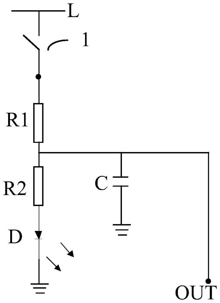
[0042] The embodiment of the present invention is optimized on the basis of the first embodiment above, as image 3 As shown, the sampling module 2 of the embodiment of the present invention includes a first resistor R1 and a second resistor R2. One end of the first resistor R1 is connected to the auxiliary switch 1, and the other end is grounded through the second resistor R2. The first resistor R1 and the second resistor The common node of the resistors R2 is the output terminal OUT of the sampling module 2 .
[0043] In an optional embodiment, the sampling module 2 also includes an indicator light D, the second resistor R2 is grounded through the indicator light D, and the indicator light is on when the auxiliary switch 1 outputs a high level signal, indicating that the knife switch is open. Conversely, when the indicator light is off, it means that the knife switch is closed.
[0044] In another optional embodiment, the sampling module 2 further includes a filter capacito...
PUM
 Abstract
Description
Claims
Application Information
 - R&D
- Intellectual Property
- Life Sciences
- Materials
- Tech Scout
- Unparalleled Data Quality
- Higher Quality Content
- 60% Fewer Hallucinations
Browse by: Latest US Patents, China's latest patents, Technical Efficacy Thesaurus, Application Domain, Technology Topic, Popular Technical Reports.
© 2025 PatSnap. All rights reserved.Legal|Privacy policy|Modern Slavery Act Transparency Statement|Sitemap|About US| Contact US: help@patsnap.com