Permanent magnet fault-tolerant motor

A permanent magnet fault-tolerant and phase-belt technology, applied in magnetic circuits, electromechanical devices, electrical components, etc., can solve problems such as the inability to achieve motor power density, low motor core utilization, and thick yoke of motor cores, so as to increase the size of the core Effects of utilization rate, permanent magnet loss suppression, and low harmonic content

Active Publication Date: 2022-04-05
HUAZHONG UNIV OF SCI & TECH
View PDF7 Cites 0 Cited by
  • Summary
  • Abstract
  • Description
  • Claims
  • Application Information

AI Technical Summary

Problems solved by technology

However, in order to effectively suppress the short-circuit current with this structure, the yoke of the motor is not saturated after the short circuit, which makes the yoke of the motor core thicker. In normal operation, the magnetic density of the yoke is small, and the motor core uses The efficiency is low, and the improvement of the power density of the motor cannot be achieved
At the same time, the copper consumption of the motor with ring winding is large, and the efficiency of the motor is low

Method used


Image

  • Permanent magnet fault-tolerant motor
  • Permanent magnet fault-tolerant motor
  • Permanent magnet fault-tolerant motor

Examples


Embodiment Construction

[0033] In order to make the object, technical solution and advantages of the present invention clearer, the present invention will be further described in detail below in conjunction with the accompanying drawings and embodiments. It should be understood that the specific embodiments described here are only used to explain the present invention, not to limit the present invention. In addition, the technical features involved in the various embodiments of the present invention described below can be combined with each other as long as they do not constitute a conflict with each other.

[0034] In the present invention, the terms "first", "second" and the like (if any) in the present invention and drawings are used to distinguish similar objects, and are not necessarily used to describe a specific order or sequence.

[0035] In order to solve the technical problems of large copper loss, low efficiency and difficulty in achieving high power density in the existing permanent magne...


PUM


Abstract

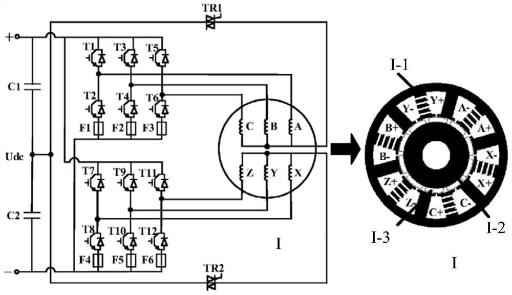
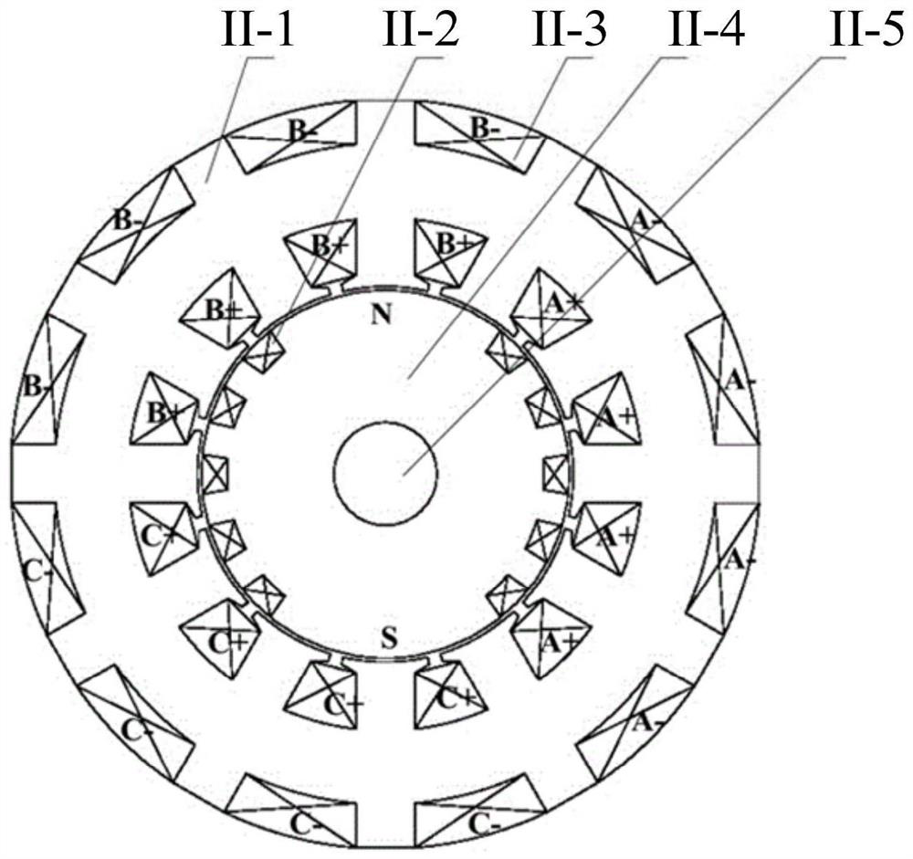
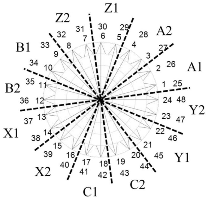
The invention discloses a permanent magnet fault-tolerant motor, and belongs to the field of fault-tolerant motors, the motor is an integer slot motor, a winding phase belt is 360 degrees/(2m), and the motor comprises m first phase belts and m second phase belts; m is the winding phase number; each phase winding corresponds to one first phase belt and one second phase belt and comprises an annular winding and a concentric winding, the annular winding is embedded in a groove below the first phase belt, and element edges on the two sides of the concentric winding are located in grooves below the two phase belts respectively; the difference between the current phases of the two phase belt lower windings corresponding to the same phase winding is 180 degrees; in each phase of winding, the q annular windings and the q concentric windings are respectively connected in series and then are connected in series to form a parallel branch; q is the slot number of each pole and each phase; the groove below the first phase belt is a large groove, the groove below the second phase belt is a small groove, and the area of the large groove is larger than that of the small groove; the large grooves incline towards the small grooves below the adjacent second phase belts on the two sides. According to the invention, the power density of the motor can be improved while the short-circuit current is effectively suppressed.

Description

technical field [0001] The invention belongs to the field of fault-tolerant motors, and more specifically relates to a permanent magnet fault-tolerant motor. Background technique [0002] With the increasingly serious problems of environmental pollution and energy depletion, the transportation industry with high carbon emissions is ushering in a comprehensive electrification change. As the core propulsion component of the vehicle, the motor has strict requirements for high power density and high reliability, especially in aerospace, electric vehicles and other fields. High power density makes the motor run under high electromagnetic load, the overall temperature of the motor is high, and the system reliability is low. Therefore, it is an urgent problem to be solved while ensuring high power density while taking into account the fault-tolerant design of the motor. [0003] In order to improve the fault tolerance capability of the motor, electrical isolation, magnetic isolati...

Claims


Application Information

Patent Timeline
Patent Type & Authority Applications(China)
IPC IPC(8): H02K3/28H02K3/12H02K3/48H02K3/52H02K1/2783
CPCY02T10/64
Inventor 李大伟王润宇曲荣海范兴纲陈健颖
Owner HUAZHONG UNIV OF SCI & TECH
Why Eureka
Try Eureka