
Innovative flash lamp driving structure

A driving structure, flash lamp technology, applied in optics, instruments, electrical components, etc., can solve problems such as low efficiency and voltage loss, and achieve the effect of improving work efficiency and saving area

Pending Publication Date: 2022-04-05
CHIPHOMER TECH SHANGHAI
View PDF0 Cites 0 Cited by
  • Summary
  • Abstract
  • Description
  • Claims
  • Application Information

AI Technical Summary

Problems solved by technology

This architecture has problems such as low efficiency in direct mode and voltage loss. For the improvement and perfection of efficiency and power consumption, this invention proposes an innovative flashlight drive structure

Method used


Image

  • Innovative flash lamp driving structure

Examples


Embodiment Construction

[0025] The following will clearly and completely describe the technical solutions in the embodiments of the present invention with reference to the accompanying drawings in the embodiments of the present invention. Obviously, the described embodiments are only some, not all, embodiments of the present invention. Based on the embodiments of the present invention, all other embodiments obtained by persons of ordinary skill in the art without creative efforts fall within the protection scope of the present invention.

[0026] It should be noted that, in the case of no conflict, the embodiments of the present invention and the features in the embodiments can be combined with each other.

[0027] The present invention will be further described below in conjunction with the accompanying drawings and specific embodiments, but not as a limitation of the present invention.

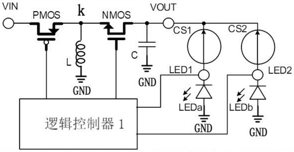
[0028] refer to figure 1 , an innovative flash driver structure, which includes:

[0029] A buck-boost power s...


PUM


Abstract

The invention relates to the field of flash lamp driving circuits, in particular to a flash lamp driving structure, which comprises a buck-boost power supply module used for converting an input voltage into an output voltage and outputting the output voltage from an output voltage end; the first constant current source branch comprises a first constant current source and a first light emitting diode which are connected between the output voltage end and the grounding end; the second constant current source branch comprises a second constant current source and a second light emitting diode which are connected between the output voltage end and the grounding end; the first constant current source controls the current of the first light emitting diode under the action of the output voltage; and the second constant current source controls the current of the second light emitting diode under the action of the output voltage. By adopting the chip architecture, the output voltage can be flexibly adjusted according to the load. And voltage drop loss in a direct connection mode does not exist, and the working efficiency is improved. And the constant current source adopts an NMOS tube, so that a considerable area can be saved.

Description

technical field [0001] The invention relates to the field of flash lamp driving circuits, in particular to a flash lamp driving structure. Background technique [0002] At present, mobile phones have become very common in people's daily life. With the rapid development of mobile phones, their functions have become more and more abundant, and their performance has become more and more powerful. In order to meet people's increasingly strict requirements for camera functions, the design and investment of mobile phones in taking pictures are also increasing. In recent years, the pixels of mobile phone cameras have also become higher and higher. In order to obtain better images, mobile phone cameras The flash function of the camera has also become more and more important. [0003] A typical mobile phone flash driver chip is a boost switching power supply plus two constant current sources. This architecture has problems such as low efficiency and voltage loss in the direct mode....

Claims


Application Information

Patent Timeline
Patent Type & Authority Applications(China)
IPC IPC(8): H05B45/345H05B45/38H05B45/375G03B15/05
Inventor 吴珂
Owner CHIPHOMER TECH SHANGHAI
Learn More