Automatic operation siphon filter tank convenient to monitor

A siphon filter, automatic operation technology, applied to loose filter material filters, filter separation, gravity filters, etc., can solve problems affecting normal water supply, uncontrollable time, insufficient filtered water, etc., to increase water treatment capacity , Avoid wasting water and save water resources

Pending Publication Date: 2022-04-08
湖南云河信息科技有限公司
View PDF3 Cites 2 Cited by
  • Summary
  • Abstract
  • Description
  • Claims
  • Application Information

AI Technical Summary

Problems solved by technology

Since the backwashing of the filter depends on the head loss of the filter sand in the filter, the time is uncontrollable. Often at the peak of water consumption, it is also the time when the backwashing of the filter is concentrated, and the amount of filtered water is insufficient, which seriously affects the normal water supply.

Method used


Image

  • Automatic operation siphon filter tank convenient to monitor
  • Automatic operation siphon filter tank convenient to monitor
  • Automatic operation siphon filter tank convenient to monitor

Examples


Embodiment 1

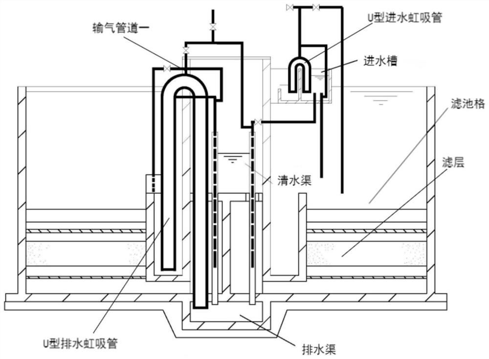
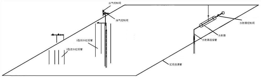
[0028] A self-operating siphon filter for easy monitoring, such as Figure 1-4 As shown, it includes the filter body, the water inlet fixed on the outer wall of the filter body by bolts, several filter cells with the same structure inside the filter body, the water outlet well fixed on the outer wall of the filter body and control system, the top outer wall of the filter grid is provided with a water distribution tank; the inner wall of each filter grid is equipped with a U-shaped drainage siphon, a U-shaped water inlet siphon, a water inlet tank, a water inlet weir, a water distribution pipe and a filter layer; the inner wall of each filter grid is provided with a monitoring unit, and the monitoring unit communicates with the control system.

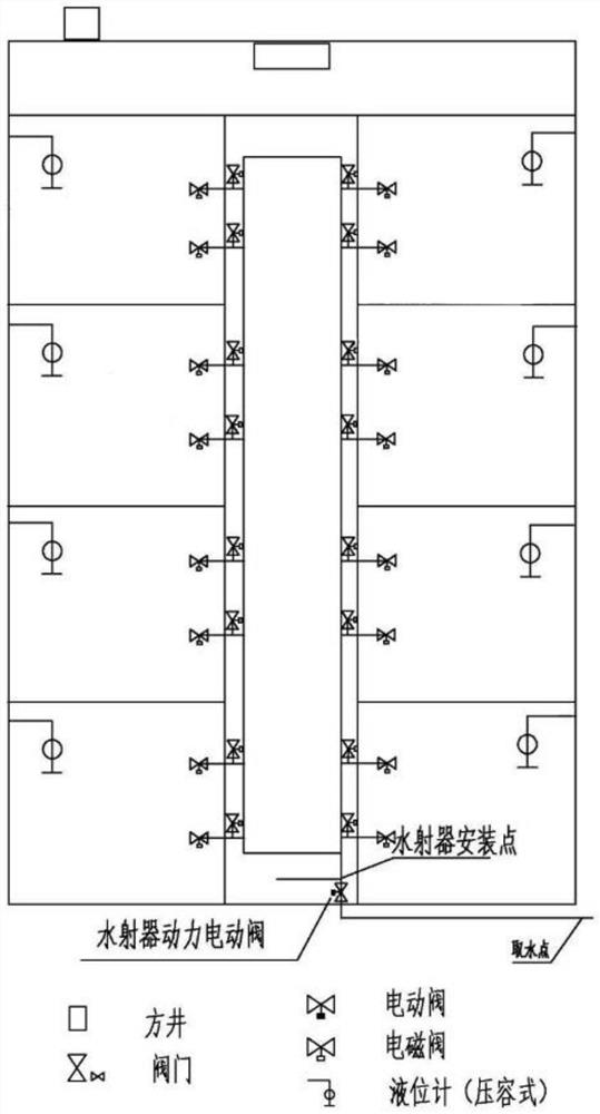
[0029] The monitoring part is composed of a pressure-capacity liquid level gauge for monitoring the operating state of each filter cell and an alarm for alarming the water level of the filter cell.

[0030] The monitoring part also inc...

Embodiment 2

[0036] A self-operating siphon filter for easy monitoring, such as Figure 1-4 As shown, in order to ensure the stability of the backwashing operation; this embodiment makes the following improvements on the basis of Embodiment 1: the monitoring part also includes a control module for automatically deploying the backwashing sequence of each filter cell in the filter body , A quality monitoring module for automatically detecting the backwashing effect of filter cells and a cleaning duration module for matching the next backwashing time according to different backwashing effects of filter cells;

[0037]The control module includes a timing block for automatically calculating the backwashing interval of each filter grid. According to the rules of the timing block, the control module automatically regulates the sequence of backwashing of each filter cell, so that only one filter cell is backwashed each time, ensuring that the total water output of other filter cells meets the flus...


PUM


Abstract

The invention discloses an automatic operation siphon filter tank convenient to monitor, and relates to the technical field of siphon filter tanks. The invention aims to solve the problem of insufficient filtered water in the peak period of water use. The water inlet is fixed to the outer wall of one side of the filter body through bolts, the filter grids are arranged in the filter body and are of the same structure, the water outlet well and the control system are fixed to the outer wall of one side of the filter body, and water distribution grooves are formed in the outer walls of the tops of the filter grids; a U-shaped drainage siphon, a U-shaped water inlet siphon, a water inlet tank, a water inlet weir, a water distribution pipe and a filter layer are arranged on the inner wall of each filter cell; a monitoring part is arranged on the inner wall of each filter cell and is in communication connection with the control system; and the monitoring part is provided with a pressure-volume liquid level meter for monitoring the running state of each filter cell. The filter tank is backwashed in the water supply valley period to ensure that all filter tank grids work normally in the water supply peak period, so that sufficient water supply quantity is ensured, and the water supply requirement is met.

Description

technical field [0001] The invention relates to the technical field of siphon filters, in particular to an automatically operated siphon filter which is convenient for monitoring. Background technique [0002] The siphon filter utilizes the principle of siphon to enter water and discharge sand washing water, thus saving two gates. During the filtration process of the filter, the dirt content of the filter layer continues to increase, and the head loss continues to increase. To maintain the water level on the outlet weir, it is necessary to overcome the increased head loss of the filter layer. When the water level in the filter rises to a predetermined height, the head When the loss reaches the maximum allowable value, it needs to be flushed, and there is no need to set up a flushing water tank or a water pump, and it can automatically control the operation of the filter tank, so it is widely used. [0003] With the gradual increase of water demand, the actual operating load...

Claims


Application Information

Patent Timeline
Patent Type & Authority Applications(China)
IPC IPC(8): B01D24/00B01D24/38B01D24/46B01D24/48
Inventor 蒋颖龄李文祺熊高丽周晨吴维乐
Owner 湖南云河信息科技有限公司
Why Eureka
Try Eureka