Cutting device for sponge

A cutting device and sponge technology, applied in cleaning methods and tools, metal processing, dust removal, etc., can solve the problems of unfavorable cutting quality, low cutting flatness, and slow cutting efficiency, so as to improve the cutting effect and improve the cleaning rate , the effect of improving efficiency

Pending Publication Date: 2022-04-08
安徽太平海绵制品有限公司
View PDF1 Cites 2 Cited by
  • Summary
  • Abstract
  • Description
  • Claims
  • Application Information

AI Technical Summary

Problems solved by technology

The sponge cutting device of this patent controls the distance between the blade and the board surface by adjusting the diameter of the blade, so as to adjust the cutting depth, but when the existing cutting device cuts the sponge, due to the elasticity of the sponge itself, the cutting is flat The accuracy is low, and the cutting efficiency is slow. At the same time, debris is generated during the cutting process, which is easy to pollute the environment and is not conducive to the quality of the cutting. Therefore, the cutting device needs to be improved.

Method used


Image

  • Cutting device for sponge
  • Cutting device for sponge
  • Cutting device for sponge

Examples


Embodiment 1

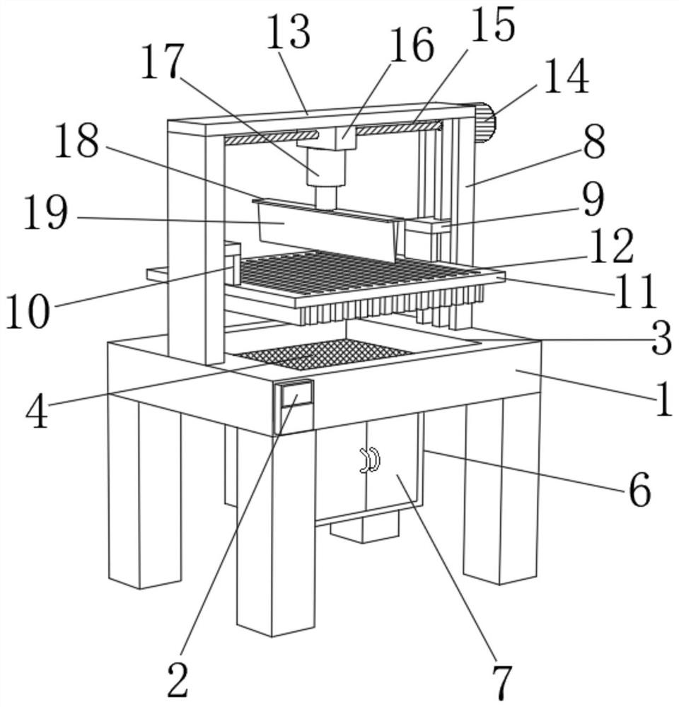
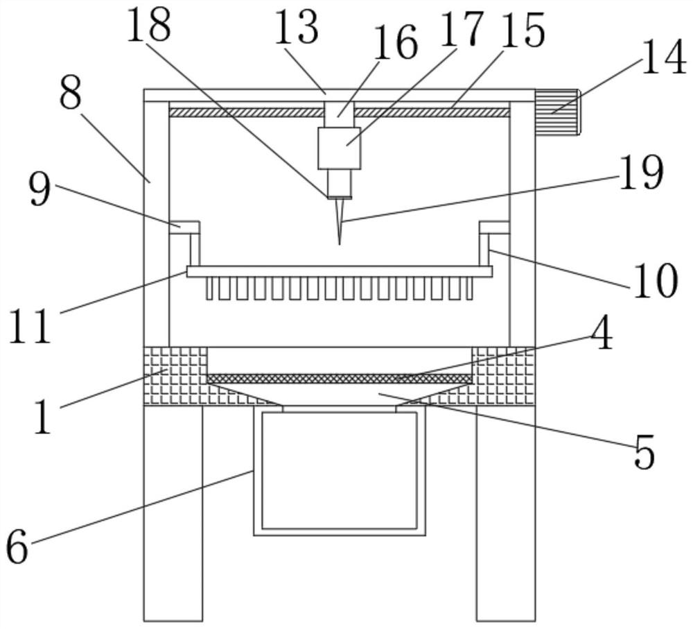
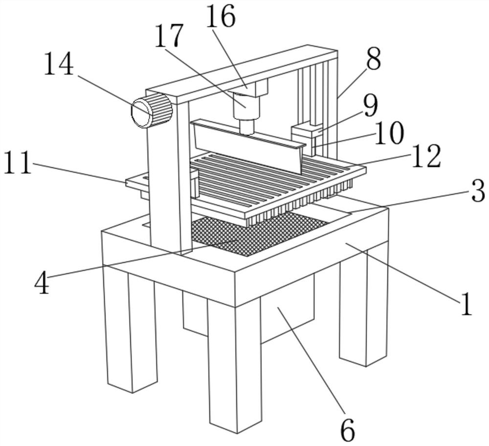
[0037] refer to Figure 1-4 , the present invention provides a cutting device for sponges, comprising a cutting table 1, a cutting groove 3 is provided at the center of the top of the cutting table 1, a support plate 4 is provided at the bottom of the cutting groove 3, and the left and right sides of the top of the cutting table 1 are The center is fixedly connected with an electric slide rail 8, and the side of the electric slide rail 8 close to the cutting groove 3 is slidably connected with a slider 9, and the side of the bottom of the slide block 9 away from the electric slide rail 8 is fixedly connected with a fixed plate 10 , the bottom of the fixed plate 10 is respectively fixedly connected to the left and right sides of the top of the guide plate 11 .

[0038] When in use, put the sponge to be cut on the support plate 4 in the cutting groove 3, start the electric slide rail 8 through the control panel 2, and the electric slide rail 8 drives the slider 9, the fixed plat...

Embodiment 2

[0041] In this embodiment, on the basis of the structural scheme disclosed in the above-mentioned embodiments, a motor 14 is fixedly connected to the top right side of the electric slide rail 8 on the right side, the driving end of the motor 14 is fixedly connected to the right end of the threaded rod 15, and The diameter is connected with a moving block 16, and the center of the bottom of the moving block 16 is fixedly connected with an electric telescopic rod 17, and the bottom of the electric telescopic rod 17 is fixedly connected with the top of the mounting plate 18, and the cutting table 1 is located inside the supporting plate 4. There is a collection tank 5, the bottom outlet of the collection tank 5 is connected to the top feed port of the dust collection box 6 through a pipe, the bottom center of the cutting table 1 is fixedly connected with the dust collection box 6, and the front side of the dust collection box 6 Two chamber doors 7 are provided.

[0042]The above ...

Embodiment 3

[0044] In this embodiment, on the basis of the structural scheme disclosed in the above-mentioned embodiments, the electric slide rail 8, the motor 14 and the electric telescopic rod 17 are all connected to the control panel 2 through signal lines, and the rear side of the control panel 2 is fixedly connected to the cutting table 1. The left end of the front side is convenient for manipulation and improves efficiency. A cutting knife 19 is arranged on the top of the mounting plate 18. The size of the cutting knife 19 is the same as that of the guide groove 12, which is convenient for the cutting knife 19 to cut the sponge and ensure the smoothness of the cutting. The top of slide rail 8 is respectively fixedly connected to the left and right ends of the bottom of the limit plate 13, the top of the moving block 16 is slidably connected to the bottom of the limit plate 13, and the left end of threaded rod 15 is connected to the right side of the electric slide rail 8 on the left s...


PUM


Abstract

The invention relates to the technical field of sponge production equipment, and discloses a sponge cutting device which comprises a cutting table, a cutting groove is formed in the center of the top of the cutting table, a supporting plate is arranged at the bottom of the cutting groove, and electric sliding rails are fixedly connected to the centers of the left side and the right side of the top of the cutting table. Sliding blocks are slidably connected to the sides, close to the cutting groove, of the electric sliding rails correspondingly, fixing plates are fixedly connected to the sides, away from the electric sliding rails, of the bottoms of the sliding blocks correspondingly, and the bottoms of the fixing plates are fixedly connected to the left side and the right side of the top of a guide plate correspondingly. According to the sponge cutting device, an electric sliding rail drives an extrusion plate to move downwards to extrude a sponge, the sponge is pressed and fixed, the problems that the cutting flatness is low and the cutting efficiency is low due to the fact that the sponge has elasticity are solved, and an electric telescopic rod drives a cutting knife to penetrate through a guide groove to cut the sponge; and the cutting smoothness is guaranteed through the limiting and guiding effects of the guiding grooves.

Description

technical field [0001] The invention relates to the technical field of sponge production equipment, in particular to a cutting device for sponge. Background technique [0002] Sponge is a porous material with good water absorption and can be used for cleaning items and cushioning products. There are many types of sponges used in industrial production, such as foamed cotton, shaped cotton, rubber cotton, memory foam, etc. Among them, foamed cotton It is widely used in the filling of pillows, mattresses, sofas and other daily necessities. It is mainly made of polymer materials such as polyether and additives for foaming and molding. The foamed sponge needs to be transferred to the cutting equipment for shape processing. [0003] Chinese patent document CN201338295Y relates to a sponge cutting device. The sponge cutting device includes: a machine base, a power mechanism, a frame and a blade. There are more than one blade installed on it, and it is connected with the transmissi...

Claims


Application Information

Patent Timeline
Patent Type & Authority Applications(China)
IPC IPC(8): B26D7/02B26D1/06B26D7/00B26D7/18B26D7/26B08B15/04
Inventor 薛秀贵
Owner 安徽太平海绵制品有限公司
Why Eureka
Try Eureka