Combination bearing and combination bearing with encoder

A combined bearing and encoder technology, which is applied in the direction of rigid support, bearing components, shafts and bearings of bearing components, can solve the problems of non-integration and poor combination precision, reduce processing links, ensure inherent precision, and beautiful appearance Effect

Pending Publication Date: 2022-04-08
浙江博盟精工轴承有限公司
View PDF0 Cites 7 Cited by
  • Summary
  • Abstract
  • Description
  • Claims
  • Application Information

AI Technical Summary

Problems solved by technology

[0003] The present invention aims at the disadvantages of non-integration and poor combination precision existing in the prior art, and provides an integrated combined bearing and

Method used


Image

  • Combination bearing and combination bearing with encoder
  • Combination bearing and combination bearing with encoder
  • Combination bearing and combination bearing with encoder

Examples


Embodiment 1

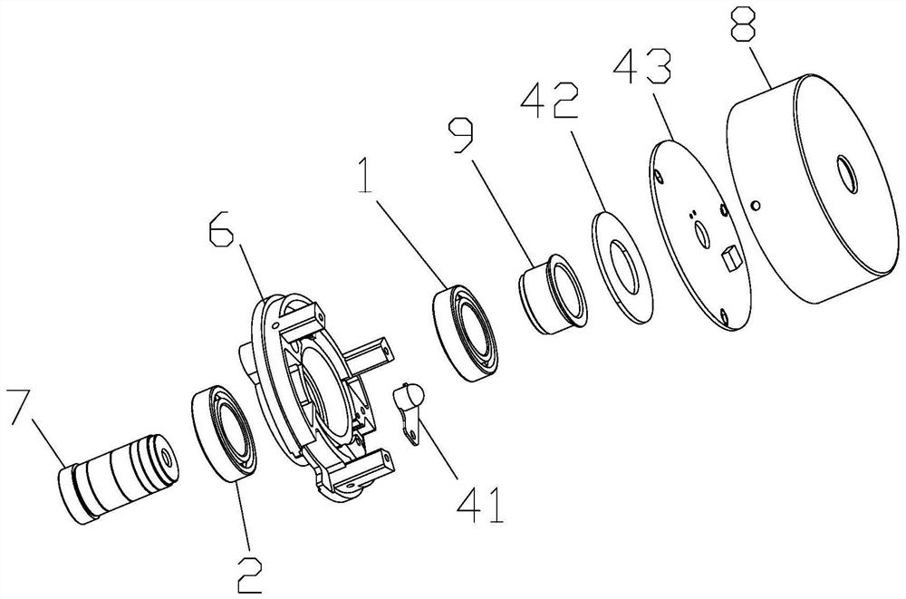
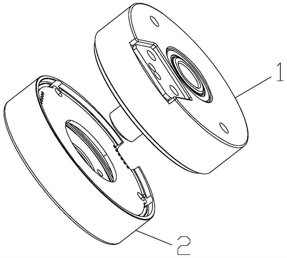
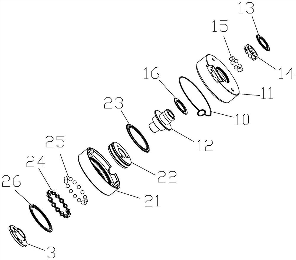
[0042] Combined bearing, including upper bearing 1 and lower bearing 2, upper bearing 1 includes upper bearing outer ring 11, upper bearing inner ring 12, first sealing ring 13, first cage 14, first steel ball 15 and second sealing ring 16 , the first cage 14 evenly separates the first steel balls 15 and places them in the grooves of the upper bearing outer ring 11 and the upper bearing inner ring 12 .

[0043] One end of the upper bearing inner ring 12 is an inner ring member 121, which is matched with the upper bearing outer ring 11; the lower bearing 2 includes the lower bearing outer ring 21, the lower bearing inner ring 22, the third sealing ring 23, the second cage 24, the second The second steel ball 25 and the fourth sealing ring 26, the second cage 24 evenly separates the second steel ball 25, and places them in the groove of the lower bearing outer ring 21 and the lower bearing inner ring 22, and the inner ring part 121 is essentially the inner ring of the bearing. R...

Embodiment 2

[0049] Combined bearing, its structure is based on Embodiment 1, the shape of the inner hole wall of the lower bearing inner ring 22 matches the outer shape of the locking sleeve 3, and the radial contact surface between the lower bearing inner ring 22 and the outer periphery of the locking sleeve 3 is On the end face 222 , the locking sleeve 3 is locked on the end face 222 of the inner ring 22 of the lower bearing.

Embodiment 3

[0051] Combined bearing, its structure is on the basis of embodiment 1, the first locking installation hole 34 is provided on the locking sleeve body, the corresponding second locking installation hole 221 is provided on the lower bearing inner ring 22, the first locking installation hole 34 is connected with the second locking installation hole 221 through a nut.

[0052] The side edge of the upper bearing outer ring is provided with a first concave-convex step 111, and the side edge of the lower bearing outer ring is provided with a second concave-convex step 211. The upper bearing outer ring 11 and the lower bearing outer ring 21 pass through the first concave-convex step 111 and the second The concave-convex steps 211 are closely matched, and the concave-convex fit is fastened. A rubber washer 10 is provided between the first concave-convex step 111 of the upper bearing outer ring and the second concave-convex step 211 of the lower bearing outer ring.

[0053] The locking...


PUM


Abstract

The invention relates to the technical field of bearings, in particular to a combined bearing which comprises an upper bearing and a lower bearing, and the upper bearing comprises an upper bearing outer ring and an upper bearing inner ring; one end of the upper bearing inner ring is an inner ring piece; the lower bearing comprises a lower bearing outer ring and a lower bearing inner ring; a shaft piece is arranged at the other end of the upper bearing inner ring, penetrates through the lower bearing inner ring and is locked on the lower bearing inner ring through a locking sleeve; and the upper bearing outer ring is tightly matched with the lower bearing outer ring. The combined bearing with the encoder further comprises an encoder assembly, the encoder assembly comprises a coded disc, a photoelectric assembly and an induction assembly, the coded disc is installed on the inner ring of the upper bearing, the induction assembly is installed on the inner bottom face of the outer ring of the lower bearing, the photoelectric assembly comprises a light source and irradiates the coded disc, and the photoelectric assembly is in circuit connection with the induction assembly. According to the technical scheme, the combined bearing is integrated, the installation links are reduced, the inherent precision of the bearing is ensured, the rotation stability is effectively improved, meanwhile, assembly and disassembly are convenient, maintenance is facilitated, the space is saved through the integrated structure, and the appearance is attractive.

Description

technical field [0001] The invention relates to the technical field of bearings, in particular to a bearing used for a bearing and a bearing with an encoder. Background technique [0002] Bearings are an important part of mechanical equipment, and the combination of encoders and bearings is becoming more and more widely used. Existing bearing encoders, such as figure 1 As shown, it includes a bearing and an encoder assembly. The bearing includes an upper bearing 1 and a lower bearing 2. The encoder assembly includes an encoder seat 6, a code disc 42, an induction component 43, a photoelectric component 41, a code disc support sleeve 9 and a copper shaft 7. And the protective cover 8, the photoelectric component 41 and the inductive part 43 are installed on the encoder, the copper shaft 7 passes through and is interference fit with the lower bearing 2, the encoder seat 6, the upper bearing 1 and the code disc support disc 9, and the code disc 42 Installed on the code disc su...

Claims


Application Information

Patent Timeline
IPC IPC(8): F16C35/06F16C33/58F16C33/30G01D5/347
Inventor 王训武聂和君
Owner 浙江博盟精工轴承有限公司
Why Eureka
Try Eureka