Vertebra interbody spring fusion cage

A fusion device and intervertebral technology, applied in the direction of spinal implants, etc., can solve the problems of large size of the fusion device, not easy to insert, and large nerve damage to peripheral organs, etc., and achieve the effect of small size and enlarged volume

Pending Publication Date: 2022-04-12
洪琦
View PDF0 Cites 0 Cited by
  • Summary
  • Abstract
  • Description
  • Claims
  • Application Information

AI Technical Summary

Problems solved by technology

[0002] At present, the existing fusion devices are large in size, not easy to insert, and cause great damage to the nerves of peripheral organs
There is a lack of a fusion cage that is easy to insert, has less damage, has an early support function, and can be changed in shape and size

Method used


Image

  • Vertebra interbody spring fusion cage
  • Vertebra interbody spring fusion cage
  • Vertebra interbody spring fusion cage

Examples


Embodiment 1

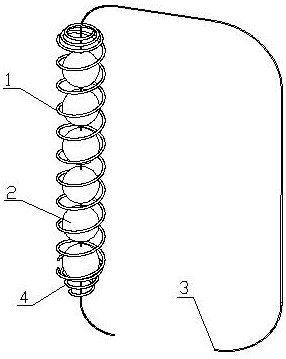
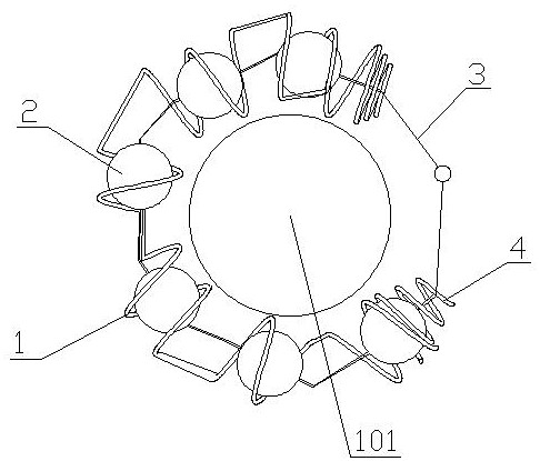
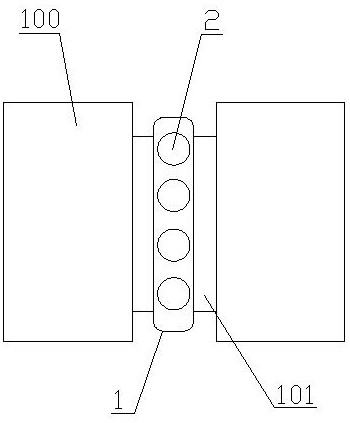
[0031] Embodiment 1: The doctor wraps the fusion device body 1 in the intervertebral space 101 between the vertebrae 100, puts a group of artificial bone implant blocks 2 on the fusion device fixing rope 3, and then implants them under pressure ( Manually lightly tap the artificial bone implant block 2) Inside the fuser body 1, cover the gland 4 after the expansion is filled, press the gland 4 into the cage body 1 and lock it tightly, and then fasten the two ends of the cage fixing rope 3 The ends are fixed by knotting, so that the fuser body 1 forms a disk shape, and the installation of the spring cage is completed.

Embodiment 2

[0032] Embodiment 2: The doctor wraps the fusion device body 1 in the intervertebral space 101 between the vertebrae 100, puts a group of artificial bone implant blocks 2 on the fusion device fixing rope 3, and then implants it under pressure ( Manually lightly tap the artificial bone implant block 2) Inside the fuser body 1, cover the gland 4 after the expansion is filled, press the gland 4 into the cage body 1 and lock it tightly, and then fasten the cage at one end of the cage fixing rope 3 The hook is fixed on the hanging ring at the other end, so that the fuser body 1 forms a disk shape, and the installation of the spring cage is completed.

[0033] One end of the fuser body 1 is a conical helix. Prevent the artificial bone implant block 2 from leaking out from the end.

[0034] The gland 4 is conical and spiral, preventing the artificial bone implant block 2 from leaking from the gland 4 .

[0035] The shape of the artificial bone implant block is spherical, rectangula...


PUM


Abstract

A spring fusion cage between vertebral bodies comprises a fusion cage body (1), a group of artificial bone implantation blocks (2), a fusion cage fixing rope (3) and a gland (4), the fusion cage body (1) is spiral, the group of artificial bone implantation blocks (2) are located in the fusion cage body (1), rope penetrating holes are formed in the artificial bone implantation blocks (2), and the fusion cage fixing rope (3) is located in the rope penetrating holes of the group of artificial bone implantation blocks (2). The gland (4) covers the end part of the fusion cage body (1); the invention has the advantages that: 1, the volume is smaller and is easy to put, and the volume can be enlarged after bone grafting; 2, a disc shape is formed, and biomechanical characteristics are better met; 3, after bone grafting, the vertebral body end plate hydroxyapatite spring (fusion cage body) and the bone grafting block are mutually fused and supported. And 4, the invalidation and infection are easy to take out by reverse rotation.

Description

technical field [0001] The invention relates to the field of medical equipment, in particular to a spring fusion device between vertebral bodies. Background technique [0002] At present, the existing fusion device has a large volume, is not easy to insert, and causes great damage to the nerves of peripheral organs. There is a lack of a fusion device that is easy to insert, has less damage, has an early support function, and can be changed in shape and size. Contents of the invention [0003] The object of the present invention is to provide a kind of intervertebral spring fusion device for the above-mentioned deficiencies. [0004] The present invention includes fusion device body, a group of artificial bone implant blocks, fusion device fixing rope and gland, [0005] The body of the fusion device is in a spiral shape, and a group of artificial bone implants are located in the body of the fusion device. There are stringing holes on the artificial bone implants, and the...

Claims


Application Information

Patent Timeline
Patent Type & Authority Applications(China)
IPC IPC(8): A61F2/44
Inventor 洪琦洪紫荊李芳
Owner 洪琦
Why Eureka
Try Eureka