

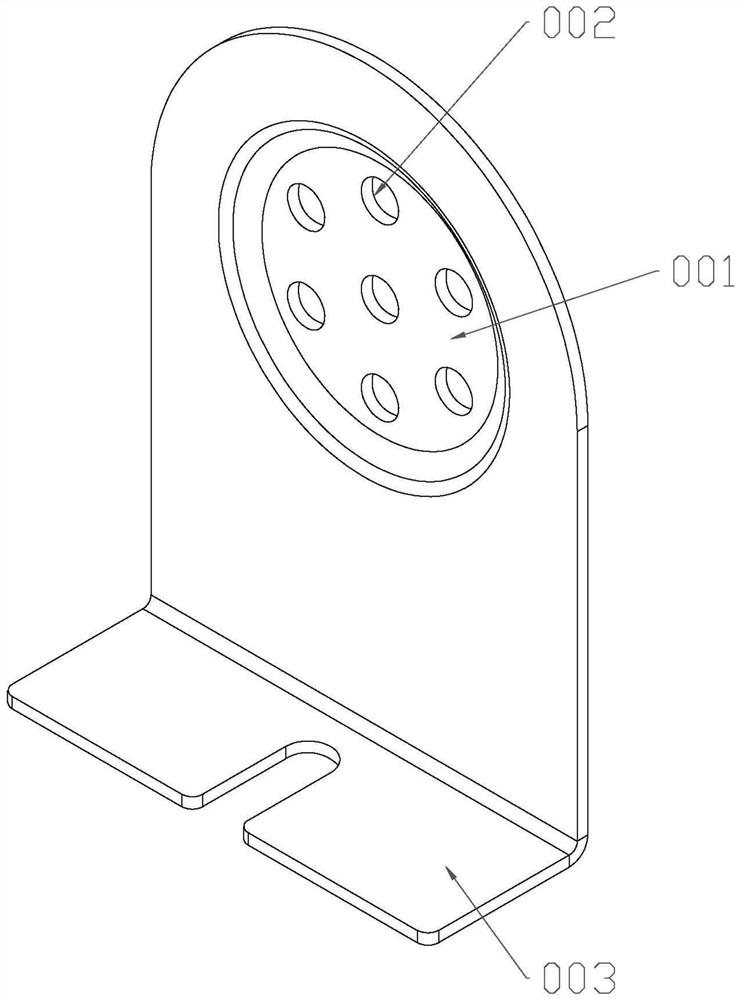
Continuous forming die for machining corrugated resistance tube support
A technology for forming molds and corrugated resistors, which is applied in the field of resistance tube processing equipment, can solve problems such as misalignment of hole positions, impact on product quality, and impact on production efficiency, and achieve accurate hole positions, good bending effects, and high production efficiency Effect
- Summary
- Abstract
- Description
- Claims
- Application Information
AI Technical Summary
Problems solved by technology
Method used
Image

Examples
Embodiment Construction
[0029] The present invention will be described in detail below in conjunction with specific embodiments and accompanying drawings.
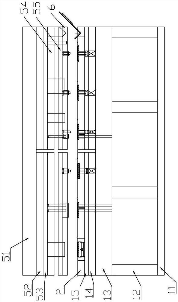
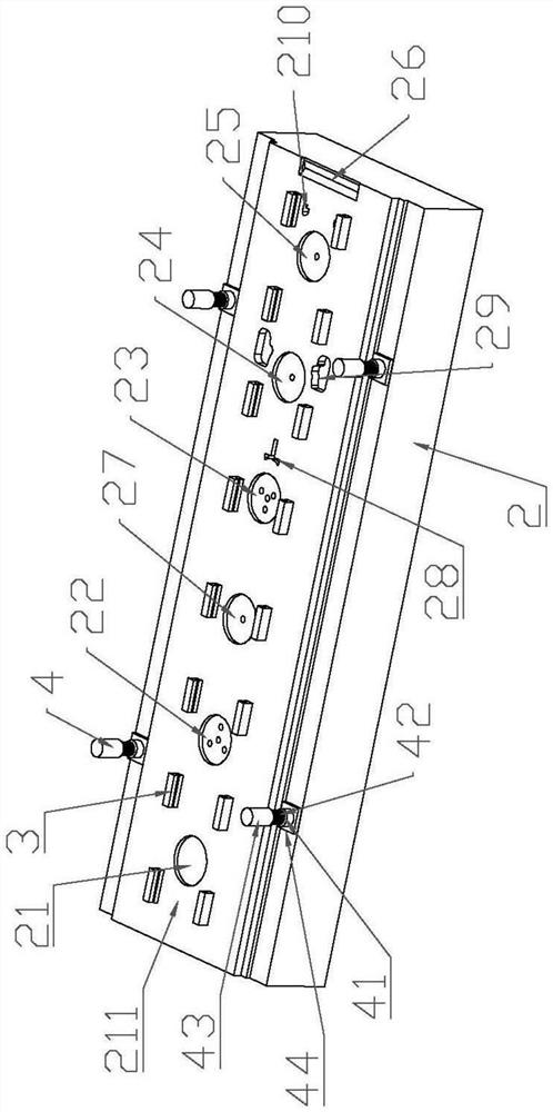
[0030] The continuous molding die of this embodiment is used to continuously complete the four processes of forging, punching, cutting and bending of the corrugated resistance tube support. Figure 2 to Figure 4 As shown, it includes a lower die set and an upper die set directly above the lower die set. The lower die set includes a lower supporting plate 11, a lower foot 12, a lower die base 13, a lower back plate 14, and a lower die set arranged sequentially from bottom to top. The backing plate 15 and the lower template 2, the lower template 2 is provided with a feeding channel 211, and the feeding channel 211 is provided with a forging positioning groove 21, a punching positioning groove, a cutting positioning groove and a bending pressure groove 26, and the side of the cutting positioning groove A lower die is provided, and the bottom of the ...
PUM
 Abstract
Description
Claims
Application Information