
Rapid wire bending mechanism

A bending mechanism and wire technology, applied in the field of mechanical bending, can solve the problems of high manufacturing cost, low production efficiency, and inability to adjust the orientation

Pending Publication Date: 2022-04-12
TANAC AUTOMATION
View PDF2 Cites 0 Cited by
  • Summary
  • Abstract
  • Description
  • Claims
  • Application Information

AI Technical Summary

Problems solved by technology

[0003] The existing wire forming machine pressing and feeding mechanism has not been able to achieve integration, the structure of the back of the mechanism is complicated, and assembly and maintenance are difficult; when forming some small-diameter wires, it is necessary to manually adjust the bending direction, and it is difficult to control the angle. It is easy to produce large deviations, and manual processing and bending wire forming, low production efficiency, high labor costs, resulting in high production costs
[0004] Chinese patent CNCN201168756Y discloses a metal wire bending machine, and Chinese patent CN202411283U also discloses a wire bending machine. These two bending machines have the advantages of high productivity, regular molding, and no scratches. The structure of the two kinds of bending machines is relatively complicated, the orientation cannot be adjusted, the bending and forming effect is poor, and the manufacturing cost is relatively high

Method used


Image

  • Rapid wire bending mechanism
  • Rapid wire bending mechanism
  • Rapid wire bending mechanism

Examples


Embodiment Construction

[0023] Specific embodiments of the present invention will be further described in detail below. It should be understood that the description of the embodiments of the present invention here is not intended to limit the protection scope of the present invention.

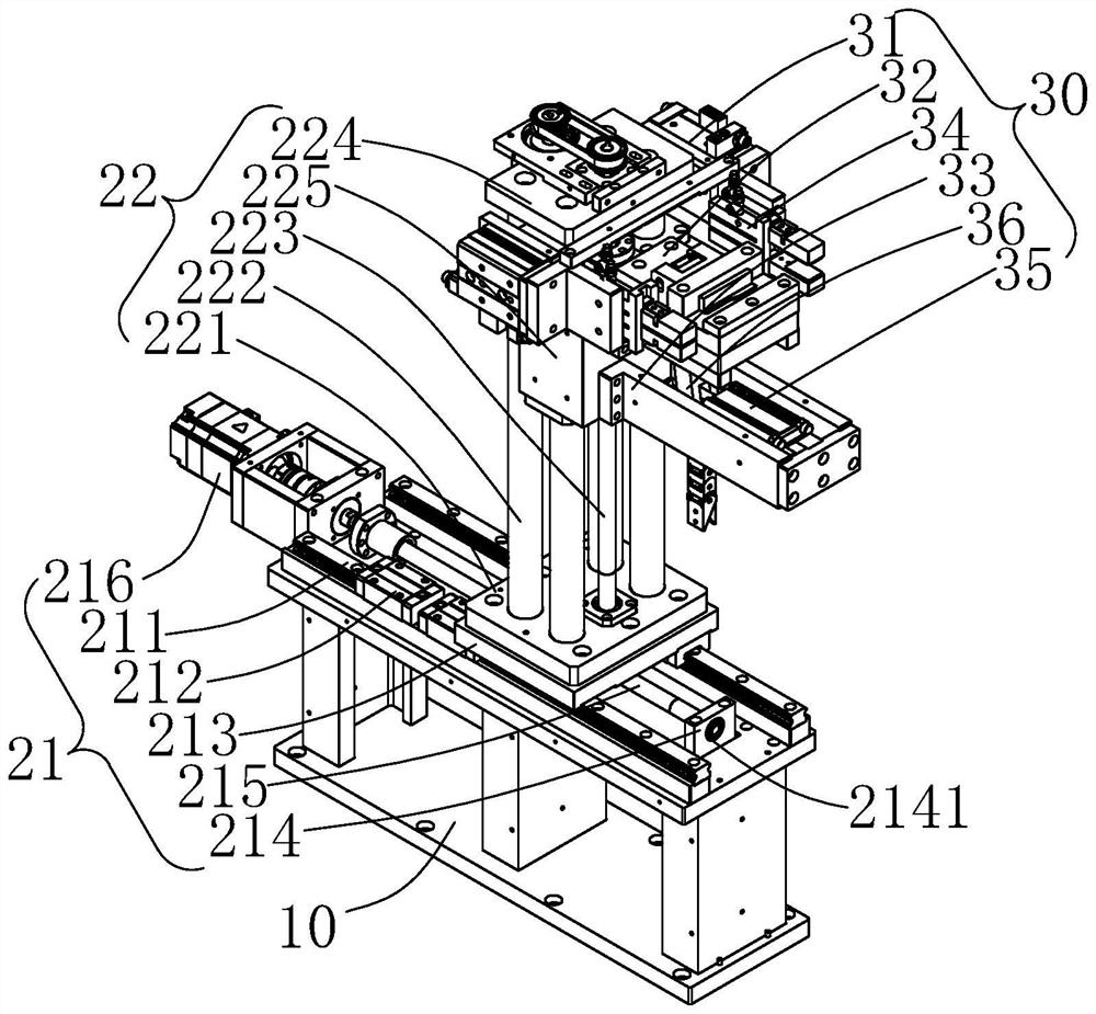
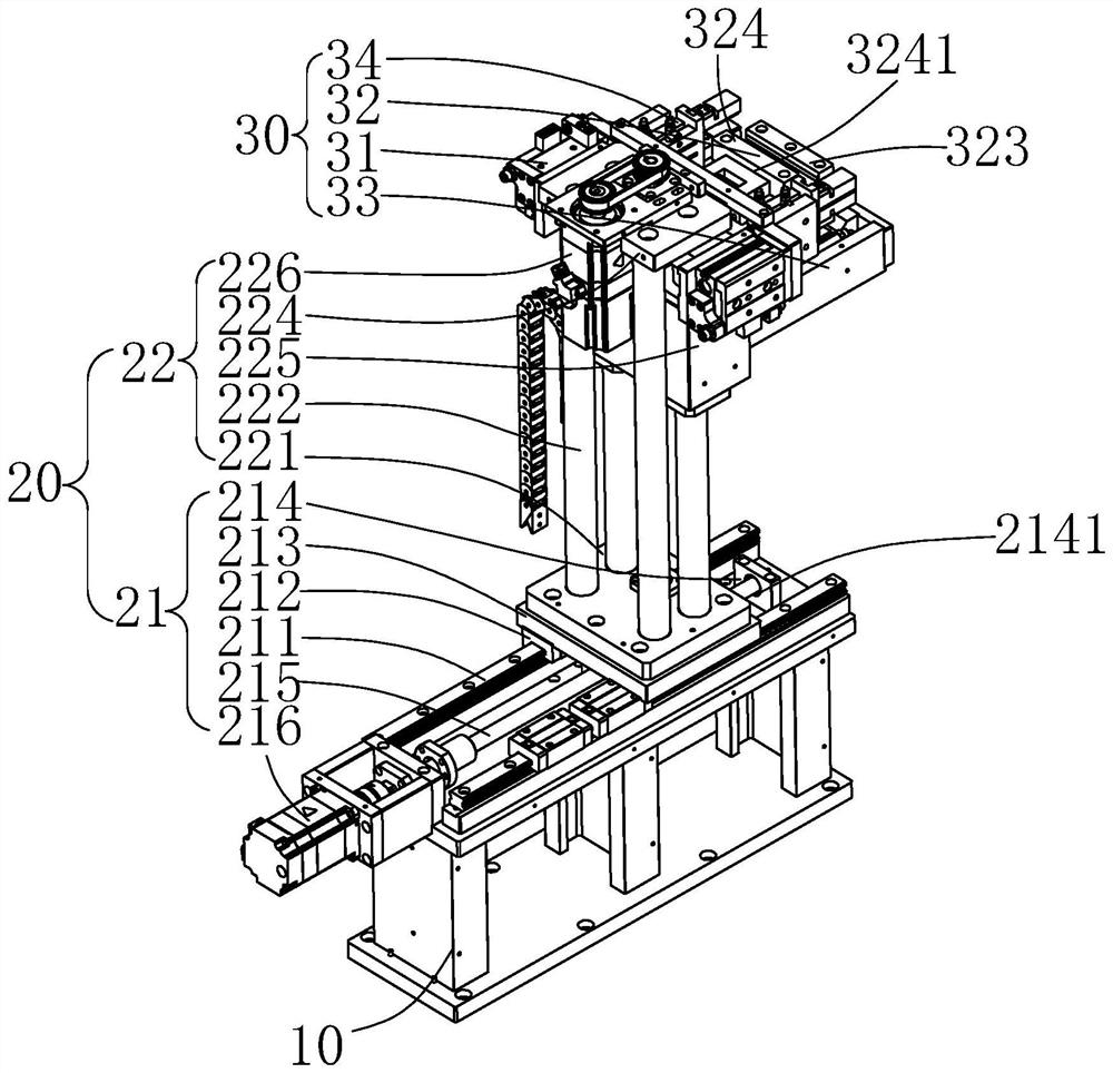
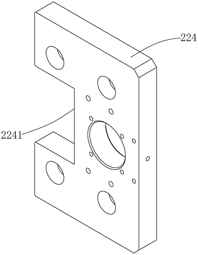
[0024] like Figure 1 to Figure 7 As shown, it is a structural schematic diagram of a rapid wire bending mechanism provided by the present invention. The rapid wire bending mechanism includes a frame 10 , an orientation adjustment mechanism 20 arranged on the frame 10 , and a bending assembly 30 arranged on the orientation adjustment mechanism 20 . It is conceivable that the rapid wire bending mechanism also includes some other functional structures, such as fastening screws, connecting cables, etc., which are known to those skilled in the art and will not be repeated here.

[0025] The frame 10 is fixed on the ground and fixed to the ground by screwing, and is used to carry the orientation adjustment mechanism 20 a...


PUM


Abstract

A rapid wire bending mechanism comprises a rack, a direction adjusting mechanism and a bending assembly. The direction adjusting mechanism comprises an X-axis machine table and a Z-axis machine table. The bending assembly comprises a first air cylinder, a line folding base and a U-shaped mounting base. The first air cylinder is provided with an L-shaped installation base, and the two second air cylinders are arranged on the L-shaped installation base. A clamping jaw is arranged at the output end of the second air cylinder, and the shaping assembly is arranged on the line folding base. A third air cylinder is arranged in the U-shaped mounting base, and the two ends of a connecting arm are connected with the third air cylinder and the shaping assembly respectively; the third air cylinder pushes one end of the connecting arm, so that the connecting arm swings, and the shaping assembly connected with the other end of the connecting arm is closed. According to the rapid wire bending mechanism, the direction adjusting mechanism is designed to adapt to wires at different positions, the to-be-machined wires are clamped and shaped through the pre-designed shaping assembly, positioning is accurate, and the shaping and bending effect is good.

Description

technical field [0001] The invention relates to the technical field of mechanical bending, in particular to a rapid wire bending mechanism. Background technique [0002] In metal wire processing, it is often necessary to bend wires of different diameters at different angles and in different directions. Usually, wire forming is mainly composed of straightening mechanism, wire feeding mechanism, pressing mechanism, bending forming and cutting mechanism and other parts. composition. [0003] The existing wire forming machine pressing and feeding mechanism has not been able to achieve integration, the structure of the back of the mechanism is complicated, and assembly and maintenance are difficult; when forming some small-diameter wires, it is necessary to manually adjust the bending direction, and it is difficult to control the angle. It is easy to produce large deviations, and the manual processing and bending of wire rods for forming has low production efficiency and high la...

Claims


Application Information

Patent Timeline
IPC IPC(8): B21F1/00
Inventor 刘佑喜吴昊王峰王一飞赵俐引沈欣尧李鑫
Owner TANAC AUTOMATION
Learn More