
Polishing device for micromotor plastic accessory production

A technology of micro-motors and plastics, applied in the direction of grinding drive devices, grinding machine parts, grinding machines, etc., can solve the problems of needing a certain amount of time, low grinding efficiency, unfavorable continuous grinding process, etc., to achieve convenient turning and grinding The effect of high efficiency and simple structure

Pending Publication Date: 2022-04-12
深圳市先锋达塑胶五金有限公司
View PDF8 Cites 4 Cited by
  • Summary
  • Abstract
  • Description
  • Claims
  • Application Information

AI Technical Summary

Problems solved by technology

[0005] Aiming at the deficiencies of the prior art, the present invention provides a grinding device for the production of micro-motor plastic accessories, which is equipped with two sets of clamping mechanisms to fix and fix different types of plastic accessories conveniently, and is convenient for plastic accessories. Flip over, do not need to suspend the grinding equipment, through the lifting and rotation of the grinding disc to grind the plastic parts, the grinding efficiency is high, the continuous grinding process is realized, and the needs of users are met, and the plastic parts grinding device is solved. Usually only fixed fixtures are set. After the plastic parts are polished, it is necessary to suspend the grinding equipment, remove the polished plastic parts and turn them over, and then polish the other side of the plastic parts. The whole process requires a certain period of pause operation, which is not conducive to Continuous grinding process, low grinding efficiency

Method used


Image

  • Polishing device for micromotor plastic accessory production
  • Polishing device for micromotor plastic accessory production
  • Polishing device for micromotor plastic accessory production

Examples


Embodiment 1

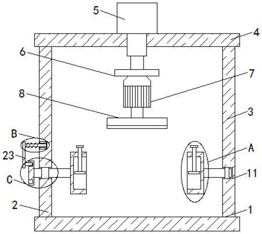
[0025] Example 1, please refer to Figure 1-4 , a grinding device for the production of micro-motor plastic parts, including a machine base 1, the top of the machine base 1 is fixedly connected with a first frame 2 and a second frame 3, and the tops of the first frame 2 and the second frame 3 The same top plate 4 is fixedly connected, the top of the top plate 4 is fixedly connected with a push rod motor 5, the output shaft of the push rod motor 5 extends through the top plate 4 to the bottom of the top plate 4 and is fixedly connected with a fixed plate 6, and the bottom of the fixed plate 6 is fixed A grinding motor 7 is connected, and the output shaft of the grinding motor 7 is fixedly connected with a grinding disc 8. Both the first frame 2 and the second frame 3 are rotatably connected with a fixed clamping mechanism, and the two fixed clamping mechanisms are compatible. Matching, the side of the first frame 2 away from the second frame 3 is slidingly connected with a posi...

Embodiment 2

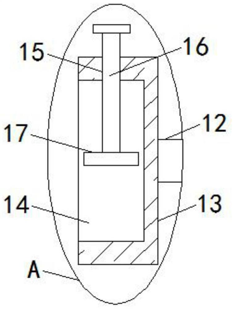
[0026] Example 2, please refer to figure 2 , the fixed clamping mechanism includes a first rotating rod 10, a second rotating rod 12, a clamping seat 13, a fastening bolt 16, a fixed plate 17 and a hand wheel 18, and the first frame 2 is provided with a rotating hole 9, and the second A rotating rod 10 is rotationally connected with the rotating hole 9, and the second frame 3 is provided with a rotating groove 11 near the side of the first frame 2, and the second rotating rod 12 is rotationally connected with the rotating groove 11, and two clamping seats 13 The sides away from each other are respectively fixedly connected with the adjacent ends of the corresponding first rotating rod 10 and the second rotating rod 12. The sides of the two clamping seats 13 close to each other are provided with clamping grooves 14. The top of the holder 13 is provided with threaded holes 15, and the two fastening bolts 16 are respectively connected to the corresponding threaded holes 15 for r...

Embodiment 3

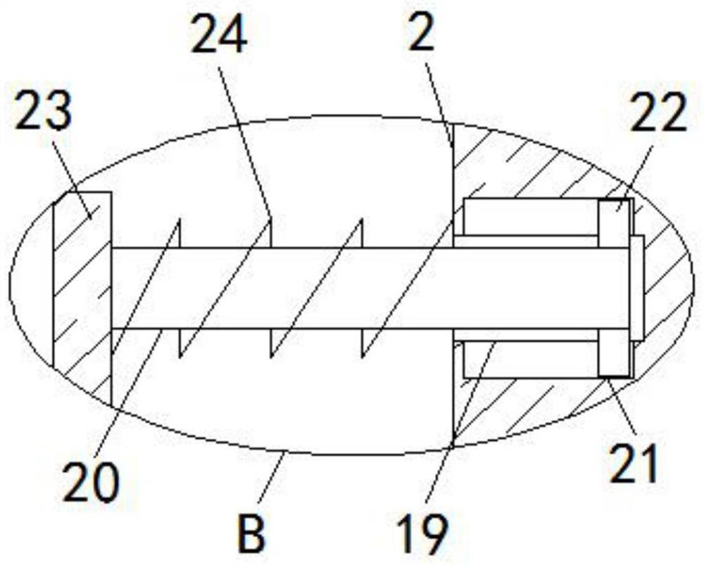
[0027] Embodiment three, please refer to image 3 , the positioning mechanism includes a positioning rod 20 and two reset blocks 22, the first frame 2 is provided with a positioning groove 19 on the side away from the second frame 3, and the positioning rod 20 is slidingly connected with the positioning groove 19, and the top of the positioning groove 19 Both the inner wall and the bottom inner wall are provided with reset grooves 21, and two reset blocks 22 are respectively slidably connected with the corresponding reset grooves 21, and the ends of the two reset blocks 22 that are close to each other extend into the positioning groove 19 and connect with the positioning rod 20. The top and bottom are fixedly connected.


PUM


Abstract

The invention relates to the technical field of grinding devices, and discloses a grinding device for micromotor plastic accessory production, which comprises a machine base, the top of the machine base is fixedly connected with a first rack and a second rack, the tops of the first rack and the second rack are fixedly connected with the same top plate, and the top of the top plate is fixedly connected with a push rod motor; an output shaft of the push rod motor penetrates through the top plate, extends below the top plate and is fixedly connected with a fixing plate, the bottom of the fixing plate is fixedly connected with a grinding motor, and an output shaft of the grinding motor is fixedly connected with a grinding disc. The plastic accessory grinding device is simple in structure and convenient to operate, plastic accessories of different types can be fixed and clamped conveniently through arrangement and rotary fixing of the two clamping mechanisms, the plastic accessories can be turned over conveniently, grinding equipment does not need to be paused, the plastic accessories are ground through lifting and rotating of the grinding disc, the grinding efficiency is high, and the practicability is high. And the continuous polishing process is achieved, and the requirements of users are met.

Description

technical field [0001] The invention relates to the technical field of grinding devices, in particular to a grinding device for the production of micro-motor plastic parts. Background technique [0002] With the rapid development of the plastic industry and the continuous improvement of plastic performance, plastic accessories have been more widely used. Plastic accessories are replacing traditional metal parts in different fields. A well-designed plastic accessory can often replace multiple traditional metal parts. , so as to achieve the purpose of simplifying the product structure and saving manufacturing costs. In order to ensure the surface quality of plastic parts, it is necessary to polish the plastic parts to remove the parting line on the surface of the plastic parts. [0003] However, the existing plastic accessories grinding device is usually only equipped with a fixed fixture. After the plastic accessories are polished, it is necessary to suspend the grinding equ...

Claims


Application Information

Patent Timeline
Patent Type & Authority Applications(China)
IPC IPC(8): B24B9/20B24B41/06B24B47/12B24B41/02B24B41/04
Inventor 汪玉峰戴香顺张雨露
Owner 深圳市先锋达塑胶五金有限公司
Learn More