
Pose optimization and motion fairing calculation method and system for robot measurement and application

A calculation method and robot technology, applied in measuring devices, design optimization/simulation, instruments, etc., can solve problems such as laser incident angle deviation, robot motion flutter, etc., and achieve the effect of controllable precision and high efficiency

Pending Publication Date: 2022-04-12
HUAZHONG UNIV OF SCI & TECH +1
View PDF0 Cites 0 Cited by
  • Summary
  • Abstract
  • Description
  • Claims
  • Application Information

AI Technical Summary

Problems solved by technology

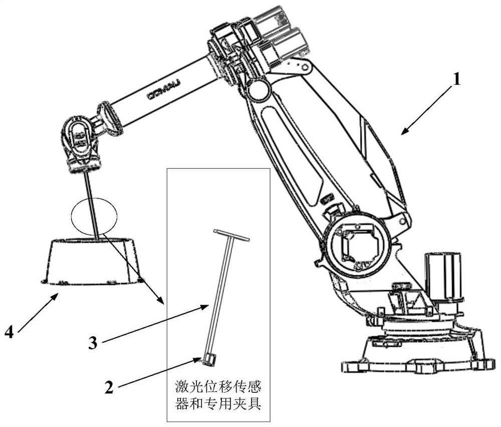
[0006] The difficulty of this kind of problem is mainly that when the robot clamps the laser displacement sensor for measurement, due to the special structure of the complex curved surface part, the laser displacement sensor is very easy to interfere with the part, and the incident direction of the laser beam when the laser displacement sensor is used for measurement is different from that of the curved surface measurement. The normal of the point cannot have a large angular deviation
Unreasonable interference avoidance will lead to robot motion chatter. How to simultaneously consider the non-interference avoidance of measurement, laser incident angle deviation and robot motion smoothness is the difficulty in solving such problems.

Method used


Image

  • Pose optimization and motion fairing calculation method and system for robot measurement and application
  • Pose optimization and motion fairing calculation method and system for robot measurement and application
  • Pose optimization and motion fairing calculation method and system for robot measurement and application

Examples


Embodiment Construction

[0059] In order to make the object, technical solution and advantages of the present invention more clear, the present invention will be further described in detail below in conjunction with the examples. It should be understood that the specific embodiments described here are only used to explain the present invention, not to limit the present invention.

[0060] Aiming at the problems existing in the prior art, the present invention provides a pose optimization and motion smoothing calculation method, system and application of robot measurement. The present invention will be described in detail below with reference to the accompanying drawings.

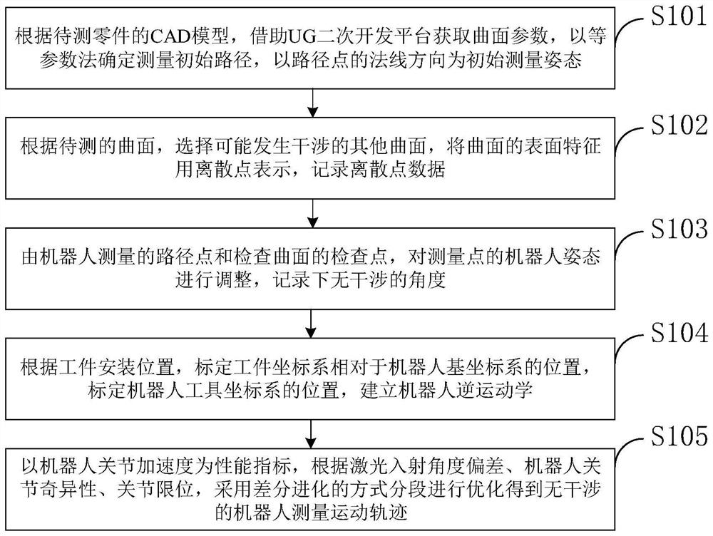
[0061] Such as figure 1 As shown, the pose optimization and motion smoothing calculation method for robot measurement provided by the embodiment of the present invention includes:

[0062] S101, according to the CAD model of the part to be measured, the surface parameters are obtained by means of the UG secondary development platfo...


PUM


Abstract

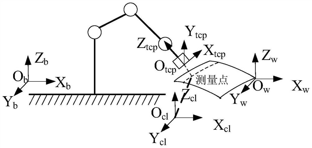
The invention belongs to the technical field of robot motion posture optimization, and discloses a robot measurement posture optimization and motion fairing calculation method and system and application, according to a CAD model of a to-be-measured part, curved surface parameters are obtained by means of a UG secondary development platform, and an equal parameter method is adopted to generate an initial path and posture information during robot measurement; selecting an interference inspection curved surface, and dispersing the inspection curved surface into data points; constructing a non-interference area for measuring the path points according to the path points measured by the robot and the feature points of the inspection curved surface; according to the workpiece mounting position, the end effector mounting position and the inverse kinematics of the robot, calculating the joint acceleration of the robot during measurement; the joint acceleration is used as an index, an axis deviation angle is measured to establish optimization, a measurement feasible area of each path point is used as a search domain, and segmented optimization is carried out by adopting a differential evolution algorithm. According to the invention, interference-free path generation and smooth movement are realized when the robot carries out measurement on the laser displacement sensor at the clamping point.

Description

technical field [0001] The invention belongs to the technical field of robot movement posture optimization, and in particular relates to a method, system and application of robot measurement posture optimization and motion smoothing calculation. Background technique [0002] At present, with the rapid development of science and technology, complex curved surfaces are widely used in aerospace, automobile, ship and other fields. The manufacture of complex curved surfaces is mostly made by casting. Affected by the difference in thermal shrinkage of different parts during the casting cooling process, the surface allowance of complex curved surfaces formed by casting is uneven and has a large fluctuation range, which requires further finishing. The removal margin is obtained by measurement. The current measurement methods are mainly divided into contact measurement and non-contact measurement. The non-contact measurement has a small working range and is not suitable for complex ...

Claims


Application Information

Patent Timeline
IPC IPC(8): B25J9/16G06F30/27G06N3/12G01B11/00G06F111/04
CPCY02T10/40
Inventor 杨吉祥漆琪曾庆双郭皓邦丁汉
Owner HUAZHONG UNIV OF SCI & TECH
Learn More