Drying air duct, washing and drying all-in-one machine and control method of drying air duct

An air duct and tuyere technology, applied in the field of washing machines, can solve the problems of low rotation speed of the inner drum, low drying efficiency, and clothes accumulation at the bottom of the drum, etc., so as to reduce the rotation time, improve the drying efficiency, and reduce the generation of clothes dander. Effect

Active Publication Date: 2022-04-12
GREE ELECTRIC APPLIANCES INC
View PDF6 Cites 0 Cited by
  • Summary
  • Abstract
  • Description
  • Claims
  • Application Information

AI Technical Summary

Problems solved by technology

[0005] The purpose of the present invention is to provide a drying air duct, a washing-drying machine and a control method for the drying air duct, so as to solve the problem in the prior art that the inner cylinder rotates at a low speed in the later stage of drying, causing the clothes to accumulate at the bottom of the cylinder. The technical problem of low drying efficiency; the many technical effects that can be produced by the preferred technical solutions among the many technical solutions provided by the present invention are detailed below.

Method used


Image

  • Drying air duct, washing and drying all-in-one machine and control method of drying air duct
  • Drying air duct, washing and drying all-in-one machine and control method of drying air duct
  • Drying air duct, washing and drying all-in-one machine and control method of drying air duct

Examples


Embodiment 1

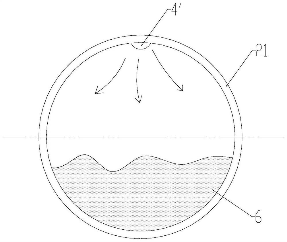
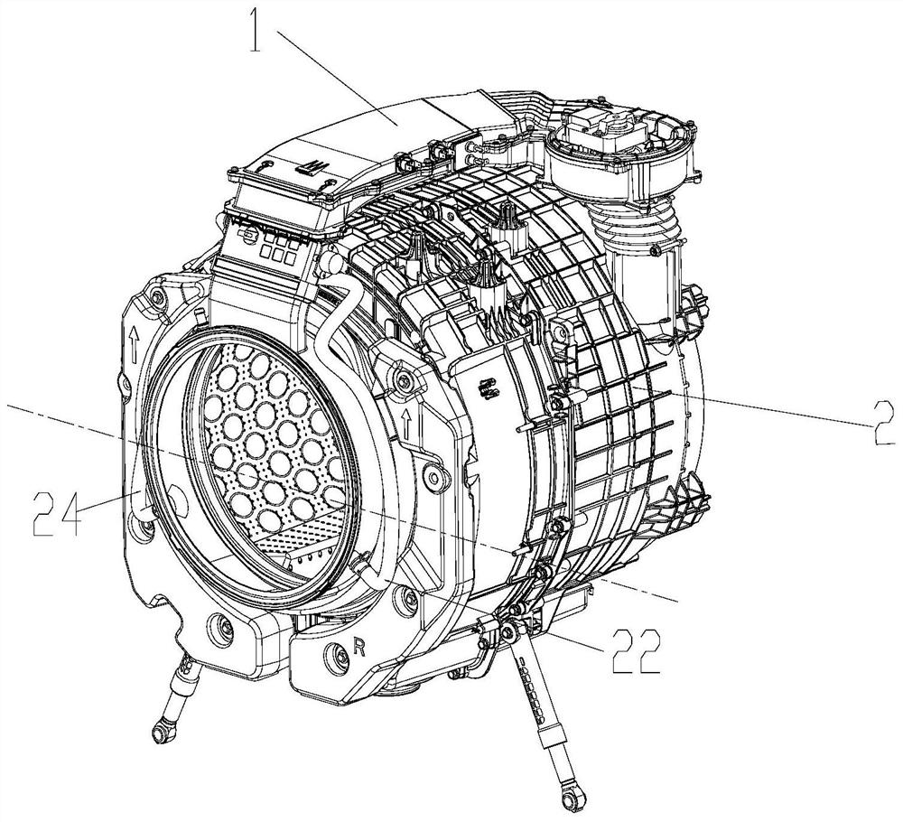
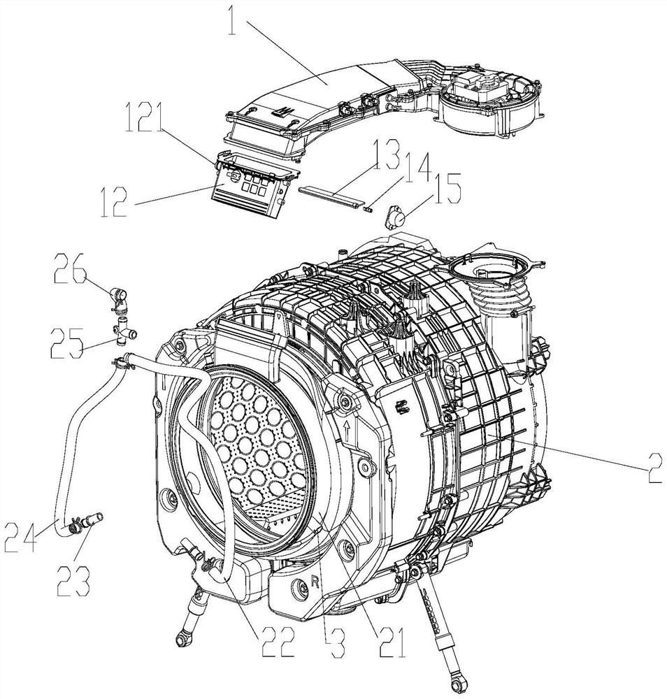
[0042] Such as Figure 2-Figure 9 As shown, this embodiment provides a drying air duct for use in a washing and drying machine, which includes an air duct 1, and a main air inlet 4 and a split air inlet both arranged on the outer door seal assembly 21 3. Among them: the main air inlet 4 and the split air inlet 3 are all connected to the air duct 1, the main air inlet 4 is located above the middle of the door seal assembly 21, and can make the wind blow into the cylinder, and all the split air inlets The air outlets 3 are all located below the middle of the door seal assembly 21, and can make the wind blow into the cylinder.

[0043] Wherein, the above-mentioned tube 2 refers to an inner tube that can rotate and accommodate clothes. In order not to affect the rotation of the drum 2 for washing, the inner wall of the drum 2 cannot be provided with the main air inlet and the split air inlet 3. The main air inlet 4 and the split air inlet 3 are located on the door seal assembly 2...

Embodiment 2

[0060] The door seal assembly 21 is located outside the cylinder 2. Since the washing and drying machine needs to wash clothes, the main air outlet and the split air outlet cannot be located on the side wall of the cylinder. In order to make the air flowing out of the split air inlet 3 blow into the cylinder as much as possible, refer to Figure 6 and Figure 7 As shown, the door seal assembly 21 of this embodiment is also provided with an air guide structure, which is located on the side of the split air inlet 3 away from the cylinder, and can reflect part of the airflow blown out by the corresponding split air inlet 3 to Inside barrel 2. Preferably, the above-mentioned air guiding structure is provided on a side of each split air inlet 3 facing away from the cylinder.

[0061] see Figure 6-Figure 8 As shown, when the wind is blown out from the split air inlet 3, part of it can be reflected into the tube by the air guide structure and blow to the clothes in the tube, and ...

Embodiment 3

[0069] This embodiment provides an integrated washing and drying machine, which includes a drum 2, a door seal assembly 21 arranged outside the drum 2, and the above-mentioned drying air duct.

[0070]The all-in-one washing and drying machine of this embodiment has the above-mentioned drying air duct, which can send air into the cylinder in multiple directions to improve the drying efficiency. The clothes are accumulated at the bottom of the tube, and the wind is blown into the tube from the split air inlet 3; part of the hot air sent by the split air inlet 3 can be blown to the clothes on the upper part of the split air inlet 3, and part of the hot air can be blown to the split air inlet. The clothes in the lower part of the tuyere 3 enable the clothes at the bottom of the drum to exchange heat with the hot air, which improves the drying efficiency, reduces the rotation time required for drying the clothes in the drum, and reduces the generation of clothes dander.


PUM


Abstract

The invention provides a drying air duct, a washing and drying all-in-one machine and a control method of the drying air duct, relates to the field of washing machines, and solves the problems that clothes are accumulated at the bottom of a drum and the drying efficiency is low due to the fact that the rotating speed of an inner drum is low in the later drying period. The drying air duct comprises an air duct body, a main air inlet and flow dividing air inlets, the main air inlet and the flow dividing air inlets are formed in a door seal assembly outside a barrel and communicate with the air duct body, the main air inlet is located in the position above the middle of the door seal assembly and can enable air to be blown into the barrel, and all the flow dividing air inlets are located in the position below the middle of the door seal assembly and can enable the air to be blown into the barrel. And the wind can be blown into the cylinder. According to the drying air duct, in the later drying period, the main air inlet is turned down or closed, when the amount of clothes in the drum is larger than that of the split-flow air inlet, part of hot air sent out by the split-flow air inlet can be blown to the clothes above the split-flow air inlet, part of hot air can be blown to the clothes below the split-flow air inlet, and therefore the clothes at the bottom of the drum can exchange heat with the hot air; and the drying efficiency is improved.

Description

technical field [0001] The invention relates to the technical field of washing machines, in particular to a drying air duct, an integrated washing and drying machine and a method for controlling the drying air duct. Background technique [0002] The existing all-in-one washing and drying machine includes an air duct, and the dry hot air formed by the heat pump system or the heater can enter the drying air duct. The upper part of the door seal is provided with an air inlet, and the hot and dry air in the drying air duct can be sent into the cylinder through the air inlet on the upper part of the door seal, and the clothes in the cylinder are dried. [0003] When the existing all-in-one washing and drying machine dries clothes, in order to make the clothes dry evenly and increase the contact area between the clothes and the hot air, the inner cylinder rotates clockwise or counterclockwise at a certain speed and turn-to-stop ratio. However, the moisture content of the clothes ...

Claims


Application Information

Patent Timeline
Patent Type & Authority Applications(China)
IPC IPC(8): D06F58/20D06F25/00D06F58/38D06F105/32
Inventor 庞志超卢苇罗克斯邢维史王九州
Owner GREE ELECTRIC APPLIANCES INC
Why Eureka
Try Eureka