Frequency-conversion hand-rubbing motor reducing clutch device and washing machine

A clutch device and washing machine technology, applied in the field of washing machines, can solve the problems of slow sliding down of the clutch shaft sleeve, blockage of the clutch sleeve, slow sliding speed of the shift fork, etc., to speed up the speed of separation and approach, and speed up the up and down sliding The effect of speed and reliability improvement

Active Publication Date: 2017-11-24
TIANJIN HAIER WASHING ELECTRICAL APPLIANCE CO LTD +1
View PDF9 Cites 0 Cited by
  • Summary
  • Abstract
  • Description
  • Claims
  • Application Information

AI Technical Summary

Problems solved by technology

[0004] Since the shift fork moves up and down by rotating around the shaft, when the shift fork pushes the positioning protrusion upward, the shift fork slides from one side of the positioning protrusion to the other side of the positioning protrusion. In the above process, the shift fork and the positioning protrusion The large sliding friction between the positioning protrusions causes the sliding speed of the shift fork to be slower, the speed of the clutch sleeve to slide upwards is slower, the speed of separation of the input sleeve and the rotor is slower, and in the washing machine, it will cause the rotation time of the washing tub Longer, affecting the use of the washing machine
On the contrary, when the shift fork no longer pushes up the positioning protrusion, the shift fork returns to the initial position. In the above process, the sliding friction between the shift fork and the positioning protrusion is large, resulting in a slow sliding speed of the shift fork, and the clutch The sliding speed of the shaft sleeve is slow, and the speed of the input shaft sleeve and the rotor is relatively slow. In the washing machine, the rotation time of the washing tub will be shortened, which will affect the dehydration effect of the clothes, and may also cause the blockage of the clutch sleeve. washing machine not working properly

Method used


Image

  • Frequency-conversion hand-rubbing motor reducing clutch device and washing machine
  • Frequency-conversion hand-rubbing motor reducing clutch device and washing machine
  • Frequency-conversion hand-rubbing motor reducing clutch device and washing machine

Examples


Embodiment 1

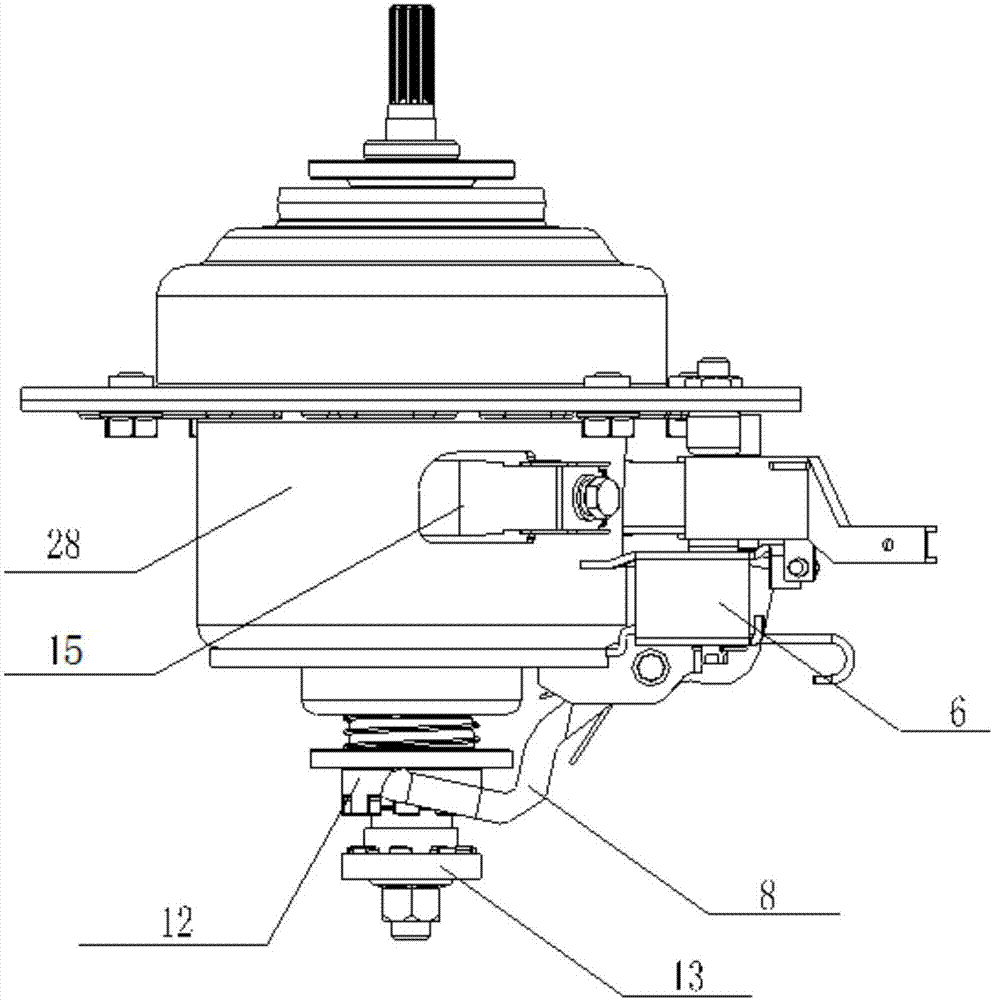
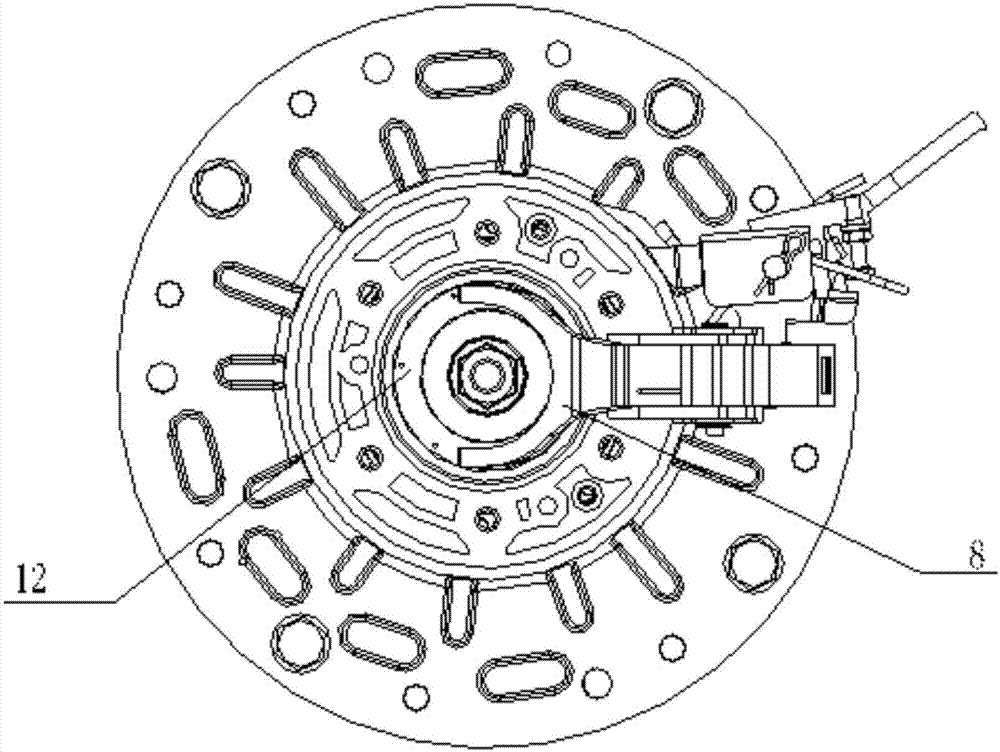
[0046] Such as Figure 1-21 As shown, in this embodiment, the input shaft 22 is sleeved with a torque bushing 13, the torque bushing 13 cannot rotate axially relative to the input shaft 22, and the torque bushing 13 and the clutch bushing 12 To realize the connection between the clutch bushing 12 and the rotor 11, the lower part of the torque bushing 13 is connected with the rotor 11. Preferably, a first damping pad 20 is provided between the lower part of the torque bushing 13 and the rotor 11 , to reduce the noise generated by the rotor 11 during rotation and the impact on the reduction clutch device.

[0047] The inner wall of the torque bushing 13 is provided with a first internal spline 23 to realize the meshing connection between the torque bushing 13 and the input shaft 22, so that the torque bushing 13 rotates with the rotation of the input shaft 22, and the rotation The top of the torque shaft sleeve 13 is provided with a first external spline 32, and the bottom of t...

Embodiment 2

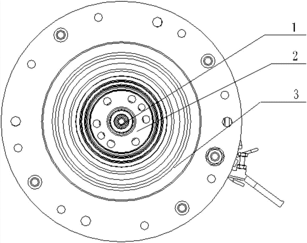
[0050] Such as Figure 1-21 As shown, in this embodiment, the top of the clutch shaft sleeve 12 is provided with a housing 28 composed of the upper end shell 3 and the lower end shell 4, and the clutch shaft sleeve 12 is sleeved with an elastically expandable clutch spring 19, the clutch spring The lower part of the clutch spring 19 is connected with the positioning protrusion 27, and the upper part of the clutch spring 19 is connected with the housing 28, so as to provide a downward sliding force to the clutch bushing 12.

[0051] The stator 10 is installed on the lower end shell 4 .

[0052] The housing 28 is provided with a fixed bracket 7, and the middle part of the shift fork 8 is connected with the fixed bracket 7 through a pin shaft 24. One end thereof is used for contacting with the positioning protrusion 27, and the other end is used for connecting with the pressing rod arranged on the housing 8. 6 are in contact with each other, and the pressing rod 6 is controlled ...

Embodiment 3

[0055] Such as Figure 1-21 As shown, in this embodiment, the oil inlet end of the oil leakage hole 26 is set outside the oil storage tank 25 and is set close to the outside of the positioning protrusion 27 .

[0056] The above arrangement prevents the lubricating grease in the oil storage tank 25 from being thrown out of the oil storage tank 25 when the clutch sleeve 12 rotates.

[0057] The specification of the oil leakage hole 26 is smaller than that of the oil storage tank 25 , so that the lubricating grease slowly flows to the contact surface between the positioning protrusion 27 and the shift fork 8 .

[0058] A plurality of oil storage grooves 25 are evenly distributed on the positioning protrusion 27 .

[0059] The oil leakage hole 26 is a through hole with a circular cross section.

[0060] A second sealing gasket 29 is provided above the positioning protrusion 27, and a positioning column 30 extending downward and corresponding to the oil storage tank 25 is provide...


PUM


Abstract

The invention relates to a frequency-conversion hand-rubbing motor reducing clutch device which comprises a clutch shaft sleeve and a poking fork contacted with the clutch shaft sleeve, wherein relative motion exists between the poking fork and the clutch shaft sleeve; and lubricating grease is applied on a contact face between the poking fork and the clutch shaft sleeve, so slide friction force between the poking fork and the clutch shaft sleeve is reduced. The invention also relates to a washing machine, wherein the frequency-conversion hand-rubbing motor reducing clutch device is disposed on the washing machine. According to the invention, the lubricating grease is applied on the contact face between a positioning convex part and the poking fork, so slide friction force between the poking fork and the positioning convex part is reduced; slide speed of the poking fork is increased; vertical slide speed of the clutch shaft sleeve is increased; separation and approaching speeds of a dewatering shaft and a rotor are increased; the difference between rotation time of a washing bucket and set time is reduced; abnormal friction sounds are reduced; reliability of the reducing clutch device is enhanced; and users' experience effects are improved.

Description

technical field [0001] The invention relates to the field of washing machines, in particular to a decelerating clutch device for a frequency-variable hand-rubbing motor. Background technique [0002] The existing deceleration clutch device includes a frequency conversion motor composed of a rotor and a stator, and an input shaft whose lower part is connected to the rotor through a nut. The outer sleeve of the input shaft is provided with an input shaft sleeve, and an oil-impregnated bearing is arranged between the input shaft and the input shaft sleeve. , so that the input shaft can rotate axially relative to the input shaft sleeve. The outer sleeve of the input shaft sleeve is provided with a clutch sleeve. The clutch sleeve cannot rotate axially relative to the input sleeve, but can slide up and down in the axial direction. The clutch sleeve Sliding down, the clutch bushing is connected with the rotor, the input bushing rotates with the rotation of the clutch bushing, the ...

Claims


Application Information

Patent Timeline
Patent Type & Authority Applications(China)
IPC IPC(8): D06F37/30
CPCD06F37/30
Inventor 田云张刚金田云龙庄仲凯唐斌
Owner TIANJIN HAIER WASHING ELECTRICAL APPLIANCE CO LTD
Why Eureka
Try Eureka