
Cargo circulating lifting device and electromagnetic power generation mechanism adopting same

A technology for lifting devices and goods, applied in the direction of conveyor control devices, conveyors, conveyor objects, etc., can solve the problems of difficult to meet the lifting requirements of goods, difficult to send goods to high places, and low operating efficiency, so as to save rotation The effect of saving time, convenient lifting and transportation, and improving operating efficiency

Active Publication Date:
View PDF9 Cites 1 Cited by
  • Summary
  • Abstract
  • Description
  • Claims
  • Application Information

AI Technical Summary

Problems solved by technology

[0005] Aiming at the deficiencies of the prior art, the present invention provides a cargo circulation lifting device and its electromagnetic generating mechanism, which has the advantages of convenience and high efficiency, and solves the problem that the existing cargo lifting platform is often used for lifting large cargo, and it is very difficult to It is difficult to deliver goods to higher floors, and the operating efficiency is low, so it is difficult to meet the needs of lifting and lowering a large number of goods

Method used


Image

  • Cargo circulating lifting device and electromagnetic power generation mechanism adopting same
  • Cargo circulating lifting device and electromagnetic power generation mechanism adopting same
  • Cargo circulating lifting device and electromagnetic power generation mechanism adopting same

Examples


Embodiment 1

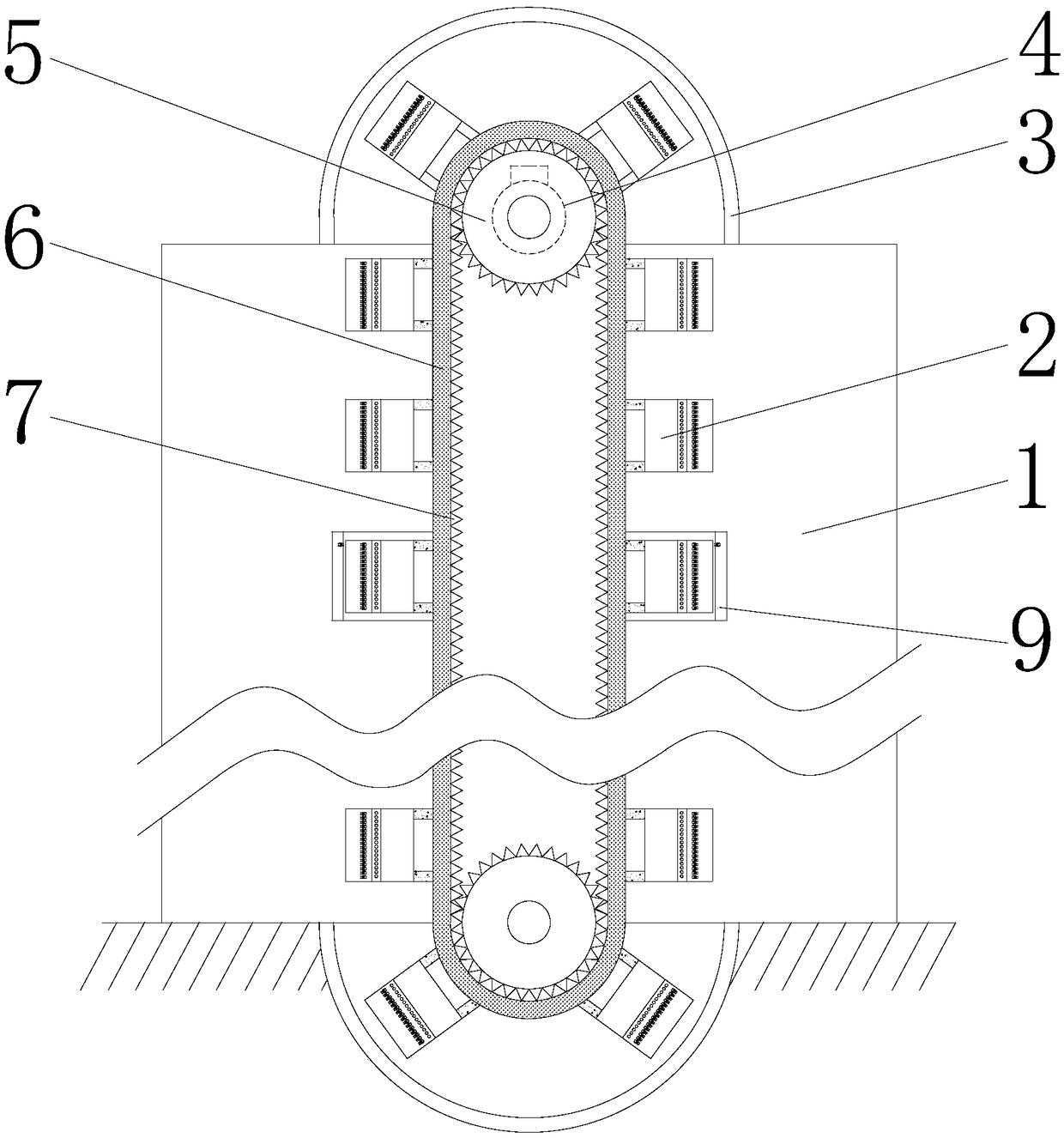
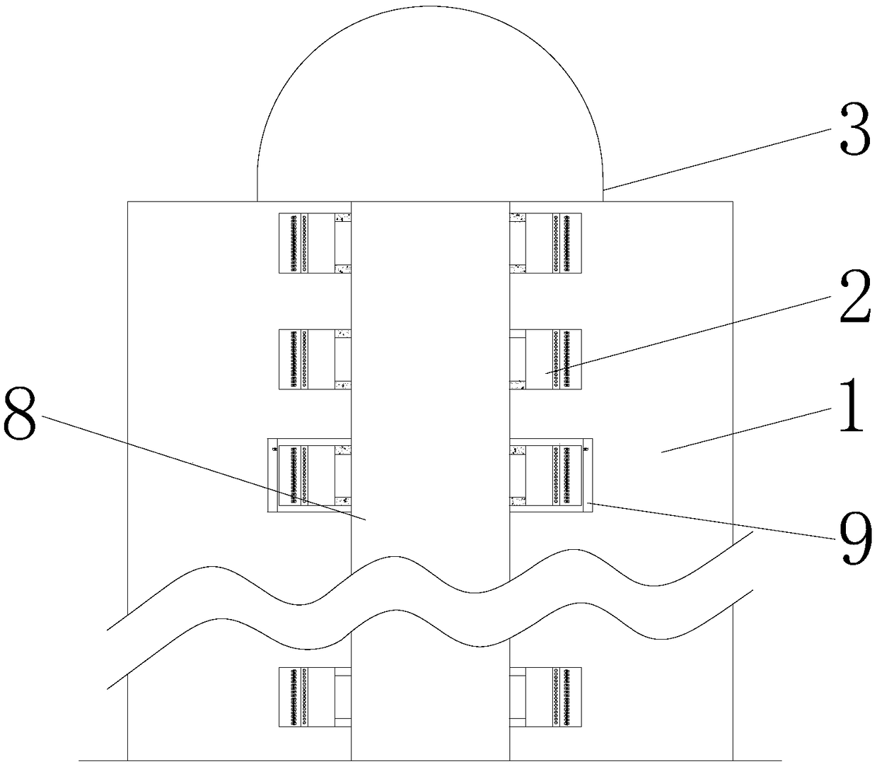
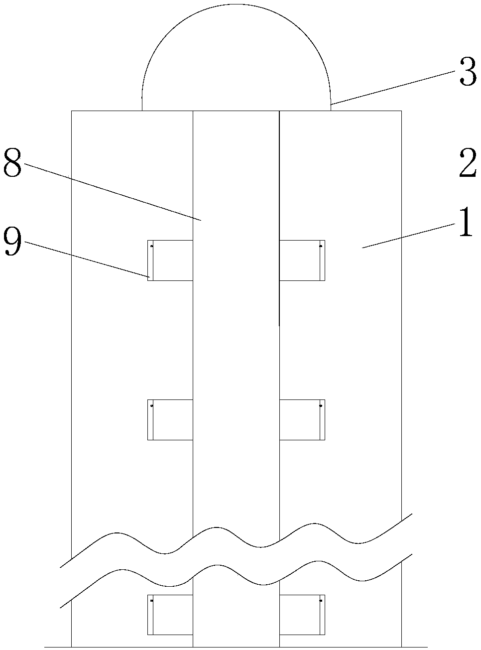
[0068] see figure 1 , figure 2 as well as image 3 , the cargo circulation lifting device of this embodiment is installed on the side of the building 1 and used to transport the cargo located on one floor of the building 1 to another floor of the building 1 . The cargo circulation lifting device includes a transmission mechanism, a detection mechanism, a controller, a strip-shaped protective box 8, two waterproof covers 3, and a plurality of storage mechanisms.

[0069] The transmission mechanism includes an endless transmission belt 6, a drive motor 4, and two runners 5. The driving motor 4 is installed on the end face of the top of the building 1, the output shaft is sheathed with a runner 5, and the other runner 5 is installed on the bottom of the building 1 in rotation. The rotating shaft of two runners 5 is perpendicular to the side of building 1, and the center line of two runners 5 is perpendicular to the ground, and two runners 5 are all meshed on the inboard of tr...

Embodiment 2

[0097] see Figure 10 , Figure 11 as well as Figure 12 , on the basis of Embodiment 1, the cargo circulation lifting device of this embodiment is an embodiment of a drive circuit.

[0098] Each positioning switch circuit includes a photoelectric switch 12, a resistor R1, a current sensor H1, a delay switch module 1, and a manual switch S1 corresponding to a button 11. The transmitter of photoelectric switch one 12 is installed on the side of storage box 2, and the receiver of photoelectric switch one 12 is installed on the fixed plate 9 that is provided with on the side of the floor of corresponding building 1. The transmitter of photoelectric switch one 12, the same interface of receiver joins. One end of the resistor R1 is connected to the other interface of the transmitter of the photoelectric switch 12, and the other end is connected to the other interface of the receiver of the photoelectric switch 12. The output two ends of the current sensor H1 are respectively co...

Embodiment 3

[0105] see Figure 13 On the basis of Embodiment 1, the cargo circulation lifting device of the present embodiment adds two guide strips 16 . The two guide strips 16 are parallel to each other and perpendicular to the ground, and the guide strips 16 are installed on the side of the building 1 . One side of the storage box 2 adjacent to the rubber column 10 is provided with a groove matching the guide bar 16 , so that the storage box 2 slides along the up and down direction of the guide bar 16 . The guide bar 16 can guide the lifting of the storage box 2, reduce the vibration of the storage box 2, and protect the goods in the storage box 2.


PUM


Abstract

The invention discloses a cargo circulating lifting device and an electromagnetic power generation mechanism adopting the same. The cargo circulating lifting device is used for transporting cargoes located on one floor of a building to the other floor of the building. The cargo circulating lifting device comprises a transmission mechanism, a detection mechanism, a controller and a plurality of storage mechanisms, wherein the transmission mechanism comprises an annular transmission belt, a driving motor, a rotating shaft and two rotating wheels perpendicular to the side surface of the building,each storage mechanism comprises a storage box and a plurality of rubber columns, the detection mechanism comprises detection units arranged in the storage boxes and indicating units installed on theside surfaces of the storage boxes. According to the cargo circulating lifting device, the transmission mechanism and the plurality of storage mechanisms are arranged so that the storage boxes can belifted to the floor needing to be reached along the transmission belt, then lifting of the cargoes is completed, the cargoes can be conveniently lifted and transported, the cargo transportation efficiency is improved, the physical labor of cargo delivery personnel is reduced, moreover, the gravity of the plurality of storage boxes on the two sides of the transmission belt is mutually balanced, then the burden of lifting is reduced, and the operation efficiency of the device is improved.

Description

technical field [0001] The invention relates to a lifting device and a power generating mechanism thereof in the technical field of cargo transportation, in particular to a cargo circulation lifting device and an electromagnetic power generating mechanism thereof. Background technique [0002] There are many high-rise buildings in the city. When the courier delivers the courier to the high floor or the takeaway delivers the food to the high floor, often when the elevator is out of service or the elevator is fully loaded, the delivery speed of the courier or the takeaway will be slow and inefficient. At the same time, it is easy to cause problems such as overwork of the takeaway or courier, which affects the shopping experience of customers. [0003] Moreover, the existing cargo lifting platforms are often used for lifting large cargoes, and it is difficult to deliver the cargos to higher floors, and the operating efficiency is low, so it is difficult to meet the lifting requ...

Claims


Application Information

Patent Timeline
Patent Type & Authority Applications(China)
IPC IPC(8): B65G17/12B65G17/30B65G43/00
CPCB65G17/12B65G17/30B65G43/00
Inventor 唐睿何进陈益民
Learn More