Multifunctional straw harvester

A multi-functional, harvester technology, which is applied in the direction of harvesters, agricultural machinery and implements, cutting equipment, etc., can solve the problems of non-adjustable direction of the feeding port of the conveying arm, incomplete adsorption effect of the fan, and failure to achieve the harvesting effect, etc. It achieves the effect of simple and novel structural design, shortened turning time, and avoids stepping on the machine

Inactive Publication Date: 2015-12-02
MUDANJIANG WANTONG MICROPORE TECH DEV
View PDF6 Cites 1 Cited by
  • Summary
  • Abstract
  • Description
  • Claims
  • Application Information

AI Technical Summary

Problems solved by technology

[0005] The purpose of the present invention is to provide a multi-functional straw harvester to solve the cumbersome process of adjusting the rotation direction of the conveying arm in the existing corn straw harvester, the direction of the spray port of the conveying arm cannot be adjusted, and at the same time it is impossible to realize green storage. The harvesting effect of both harvesting and yellow storage harvesting and the incomplete adsorption effect of the fan

Method used


Image

  • Multifunctional straw harvester
  • Multifunctional straw harvester
  • Multifunctional straw harvester

Examples


specific Embodiment approach 1

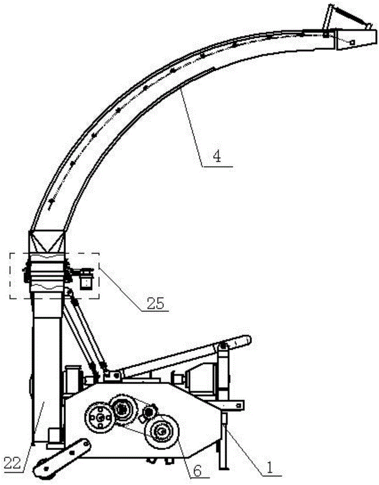
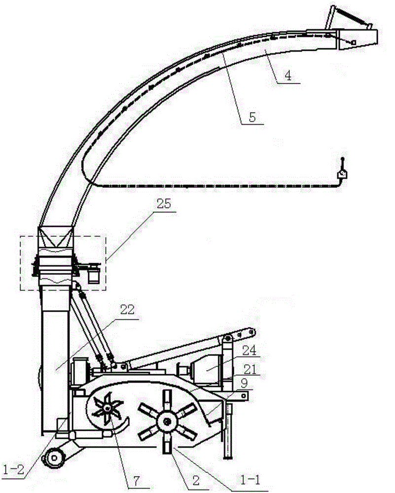
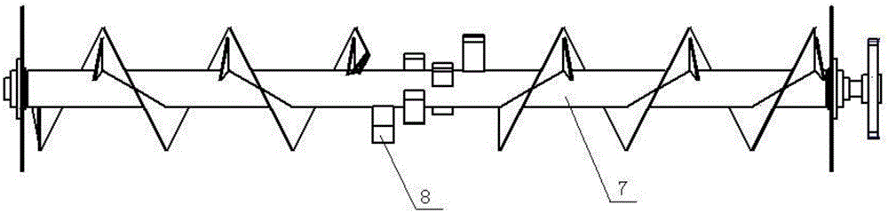
[0027] Specific implementation mode one: combine figure 1 , figure 2 , image 3 , Figure 4 , Figure 5 , Figure 6 , Figure 7 and Figure 8 Describe this embodiment, this embodiment comprises main engine shell 1, picking up and crushing rotary knife 2, pick-up roller 3, blower fan 22, conveying auger 7 and a plurality of feeding blades 8, and the front end processing of described main engine shell 1 is provided with obliquely The feeding port 1-1, the rear end of the main machine shell 1 is processed with a feeding port 1-2, the feeding port 1-2 is connected with the fan 22, the picking and crushing rotary knife 2, the picking roller 3 and the The conveying auger 7 is located in the shell of the main engine 1, and the conveying auger 7 is arranged near the feeding port 1-2. The material blade 8, the pick-up roller 3 is arranged close to the material inlet 1-1, and the pick-up and crushing rotary knife 2 is arranged on the pick-up roller 3, and it is characterized in ...

specific Embodiment approach 2

[0030] Specific implementation mode two: combination figure 1 , figure 2 and Figure 6 Describe this embodiment mode, the top end of described feeding arm 4 in this embodiment mode is a material injection port, and described manual adjustment device 5 is arranged at the material injection port place, and described manual adjustment device 5 comprises block 5-1, extension spring Bracket 5-2, extension spring 5-3, tension bar 5-4 and manual control valve 5-5, described stopper 5-1 is facing the material injection opening, and the upper end face of stopper 5-1 is connected with the feeding arm 4 The tube wall of the tube is hinged, the extension spring bracket 5-2 is fixedly connected between the feeding arm 4 and the stopper 5-1, the extension spring 5-3 is arranged on the extension spring bracket 5-2, and the tension bar 5-4 Arranged along the length direction of the feeding arm 4, one end of the tie bar 5-4 is detachably connected to the block 5-1, and the other end of the ...

specific Embodiment approach 3

[0033] Specific implementation mode three: combination figure 1 and Figure 7 Describe this embodiment, the automatic rotating device 25 of conveying arm described in this embodiment includes hydraulic motor 11, driving sprocket 12, driven sprocket 13, chain 14, swivel joint, outer support sleeve 17, inner support sleeve 18 , the bearing 19 and the connecting frame 20, the outer support sleeve 17 and the inner support sleeve 18 are coaxially arranged, the bottom end of the inner support ring 18 is sleeved in the outer support ring 17, the inner support ring 18 and the outer support ring 17 Bearings 19 are arranged between them, the top end of the inner support sleeve 18 is fixedly connected with a rotary joint, the outer support ring 17 is detachably connected with the hydraulic motor 11 through the connecting frame 20, and the output shaft of the hydraulic motor 11 is set with a driving chain Wheel 12, the driven sprocket 13 is set on the inner support sleeve 18 and is fixed...


PUM


Abstract

The invention discloses a multifunctional straw harvester, and relates to a straw harvester. The multifunctional straw harvester is used for solving the problems that when the rotating direction of a material conveying arm in an existing corn straw harvester is adjusted, the process is complex, the direction of a spraying nozzle of the material conveying arm can not be adjusted, the ensilage and yellow corn silage simultaneous harvesting effect can not be achieved, and the adsorption effect of a draught fan is not thorough. In the multifunctional straw harvester, a speed reducer is located on one side of a main machine shell, an output shaft of the speed reducer penetrates through the main machine shell to be connected with one end of a picking roller, a second-stage speed reduction device is located on the other side of the main machine shell and connected with the other end of the picking roller, an automatic rotating device used for a material conveying arm is arranged between a draught fan and the material conveying arm, a manual adjusting device is arranged on the material conveying arm, a supporting frame is fixedly connected into the main machine shell and located above a picking and smashing rotary cutter, an ensilage cover plate and a yellow corn silage cover plate are both arranged on the supporting frame, multiple rows of exhaust openings are evenly machined in the yellow corn silage cover plate in the thickness direction of the plate face of the yellow corn silage cover plate, and the yellow corn silage cover plate comprises a front cover body and an upper cover plate. The multifunctional straw harvester is used for harvesting straw.

Description

technical field [0001] The invention relates to a multifunctional straw harvester. Background technique [0002] In recent years, the development and utilization of biomass energy has been paid more and more attention by countries all over the world. my country is a developing agricultural country. Under the dual pressure of economic growth and environmental protection, the development of biomass energy conversion technology is an inevitable requirement for the sustainable development of my country's economy. The traditional human fuel biomass is converted and processed through mechanical compression technology to improve the utilization of crop straws, actively develop the processing industry using straws as raw materials, and orderly develop bioenergy using straws as raw materials. [0003] At present, my country produces more than 700 million tons of straw every year, and harvests more than 85 million tons of straw every year, only 5% of which is used for comprehensive u...

Claims


Application Information

Patent Timeline
Patent Type & Authority Applications(China)
IPC IPC(8): A01D45/02A01F29/01A01F29/02A01F29/09
Inventor 楚明孔德元陈茜池洪友
Owner MUDANJIANG WANTONG MICROPORE TECH DEV
Why Eureka
Try Eureka