Eureka AIR delivers breakthrough ideas for toughest innovation challenges, trusted by R&D personnel around the world.

Anti-tilting cleaning-free comb plate telescopic device

A telescoping device and comb-tooth plate technology, which is applied to bridge parts, bridges, buildings, etc., can solve problems such as increased noise, tooth plates that cannot be restored, and hazards to driving safety, and achieve the effect of reducing gaps and avoiding the possibility

Pending Publication Date: 2022-04-12
HEBEI BAOLI ENG EQUIP GRP CO LTD
View PDF0 Cites 0 Cited by
  • Summary
  • Abstract
  • Description
  • Claims
  • Application Information

AI Technical Summary

Problems solved by technology

One is that during use, the movable tooth plate of the ordinary comb telescopic device will warp due to various reasons such as load or settlement, resulting in damage to the tooth plate, increased noise, and even endangering driving safety
Second, during the use of comb plate expansion joints, dust and gravel will accumulate in the tooth plate gaps
Gravel and dust will enter the lower part of the tooth plate, causing the tooth plate to be lifted and unable to recover
The third is that the existing anti-lifting comb plate telescopic device adopts the introduction of vertical restraint force to limit the warping, but because of its structural design, gaps cannot be avoided, causing gravel and dust to enter the gap, resulting in the gap being unable to recover

Method used


Image

  • Anti-tilting cleaning-free comb plate telescopic device
  • Anti-tilting cleaning-free comb plate telescopic device
  • Anti-tilting cleaning-free comb plate telescopic device

Examples


Embodiment

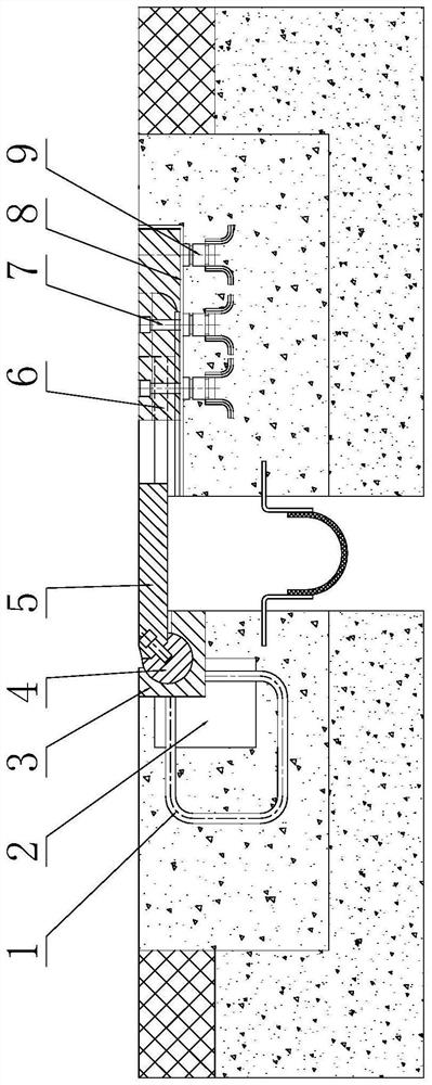
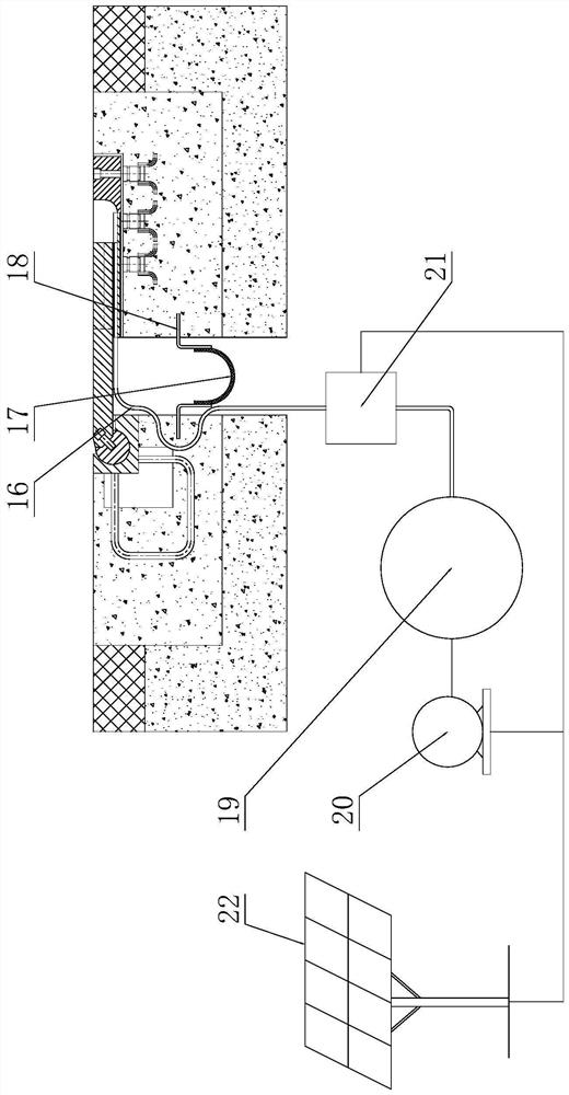
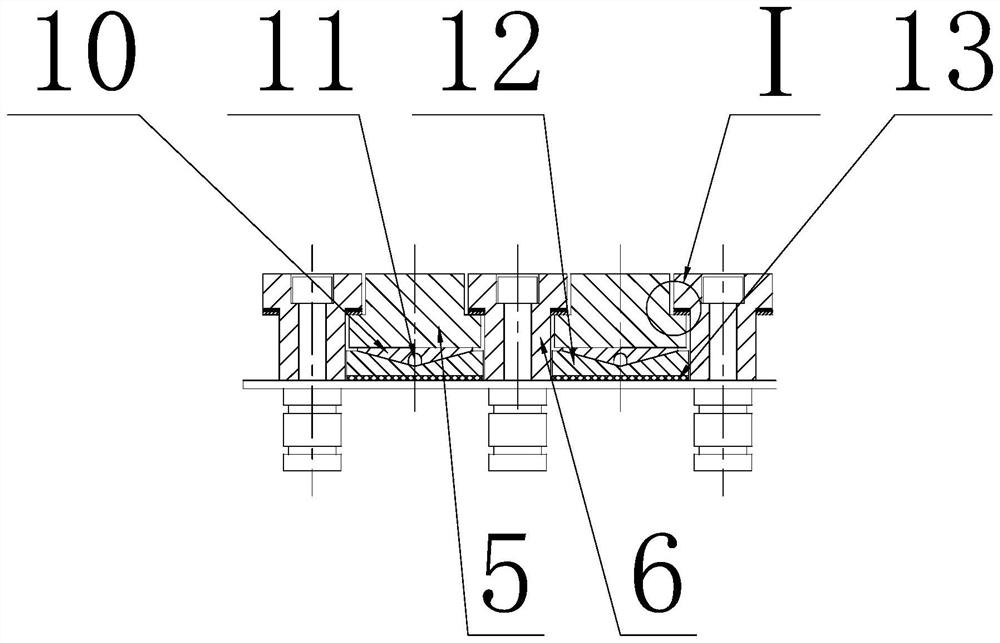
[0040] The overall structure of this embodiment is as shown in the figure, which includes a movable comb plate 5 whose root is connected to the beam end or abutment on one side of the expansion joint and whose front part overlaps the expansion joint, and its comb teeth are opposite to and fixed on the expansion joint. On the other side beam end or the fixed comb plate 6 of the bridge abutment, there is a fixed comb plate backing plate 8 under the overlapping part of the movable comb plate 5 and the fixed comb plate 6, and a rubber waterstop 17 is installed in the expansion joint ; The beam end or abutment located on the side of the root of the movable comb plate 5 is provided with a rotating sleeve 3 coaxial with the expansion joint, and the rotating sleeve 3 is fitted with a rotating shaft 4, and the root of the movable comb plate 5 is connected to the rotating shaft 4. It is fixed and can rotate along the rotating sleeve 3. There is a corner gap between the lower surface of t...


PUM


Abstract

The invention belongs to a telescopic device, and particularly relates to an anti-tilting cleaning-free comb plate telescopic device. The root of the movable comb plate is connected with one side beam end or a bridge abutment, the front portion of the movable comb plate is in lap joint with the expansion joint, the fixed comb plate is opposite to comb teeth of the movable comb plate and fixed to the other side beam end or the bridge abutment, a fixed comb plate base plate is arranged below the lap joint portion of the two comb plates, and a rubber water stop belt is arranged in the expansion joint. A rotating sleeve coaxial with the expansion joint is arranged at the beam end or the bridge abutment on one side of the root of the movable comb plate, a rotating shaft is rotatably matched in the rotating sleeve, the root of the movable comb plate is fixed to the rotating shaft and can rotate along the rotating sleeve, and a corner gap is formed between the lower surface of the root of the movable comb plate and the beam end or the bridge abutment below the movable comb plate. An outlet of the ventilation pipe is located in the lower portion of the movable comb plate and / or the fixed comb plate and faces the space defined by the comb teeth of the movable comb plate and / or the fixed comb plate. The comb plate solves the problem that in the prior art, a toothed plate is prone to upwarp to be damaged, and has the advantages that the toothed plate is not prone to upwarp, and sundries are not prone to accumulation in gaps of the comb plate.

Description

technical field [0001] The invention belongs to a telescopic device, in particular to an anti-lifting and cleaning-free comb tooth plate telescopic device. Background technique [0002] With the deepening of road and bridge traffic construction, as one of the important types of bridge expansion devices, the comb plate expansion device has been widely used due to its low noise and driving comfort. "General Technical Conditions for Highway Bridge Expansion Devices" (JT / T327-2016) puts forward clear requirements for the basic structure, classification, product performance, manufacturing materials and testing methods of comb plate expansion devices. As the use time increases, some disadvantages of the comb telescopic device gradually appear. One is that during use, the movable tooth plate of the ordinary comb telescopic device will warp due to various reasons such as load or settlement, resulting in damage to the tooth plate, increased noise, and even endangering driving safety...

Claims


Application Information

Patent Timeline
Patent Type & Authority Applications(China)
IPC IPC(8): E01D19/06
Inventor 王正张兴赵九平蒋文希陈政魏春晶王义杰国彤刘凯戎建丁赵志磊张建张建宁
Owner HEBEI BAOLI ENG EQUIP GRP CO LTD
Why Eureka
Eureka Blog
Learn More