Construction machine

A construction machinery and wall technology, which is applied in the field of construction machinery, can solve the problems of cab rigidity drop, failure to consider fracture, etc., and achieve the effect of suppressing rigidity drop

Pending Publication Date: 2022-04-12
KOBELCO CONSTR MASCH CO LTD
View PDF5 Cites 0 Cited by
  • Summary
  • Abstract
  • Description
  • Claims
  • Application Information

AI Technical Summary

Problems solved by technology

When the part near the corner breaks, the rigidity of the cab will decrease
In addition, JP-A-2010-270557 (Patent Document 3), JP-A 2010-255215 (Patent Document 4), and JP-A 2020-169454 (Patent Document 5) respectively disclose the use of construction machinery. The structure of the cab, but without taking into account the restraint of breakage in the vicinity of the lower corner of the window edge

Method used


Image

  • Construction machine
  • Construction machine
  • Construction machine

Examples


no. 1 Embodiment approach ]

[0031] figure 1 It is a side view showing the hydraulic excavator 10 according to the first embodiment of the present invention. Hydraulic excavator 10 is an example of a construction machine. like figure 1 As shown, a hydraulic excavator 10 includes an undercarriage 11 , an upper revolving unit 12 rotatably supported by the undercarriage 11 , a working device 13 , and a plurality of hydraulic actuators.

[0032] The upper slewing body 12 includes an upper frame 20 rotatably supported by the lower traveling body 11 , a cab 30 supported by the upper frame 20 , and a counterweight 29 disposed behind the cab 30 .

[0033] The working device 13 includes a boom 14 supported up and down by the upper frame 20 , an arm 15 swingably supported by the distal end of the arm 14 , and a bucket 16 swingably supported by the distal end of the arm 15 .

[0034] The plurality of hydraulic actuators include: the boom cylinder 17, which operates to receive the supply of hydraulic oil from a hy...

no. 2 Embodiment approach ]

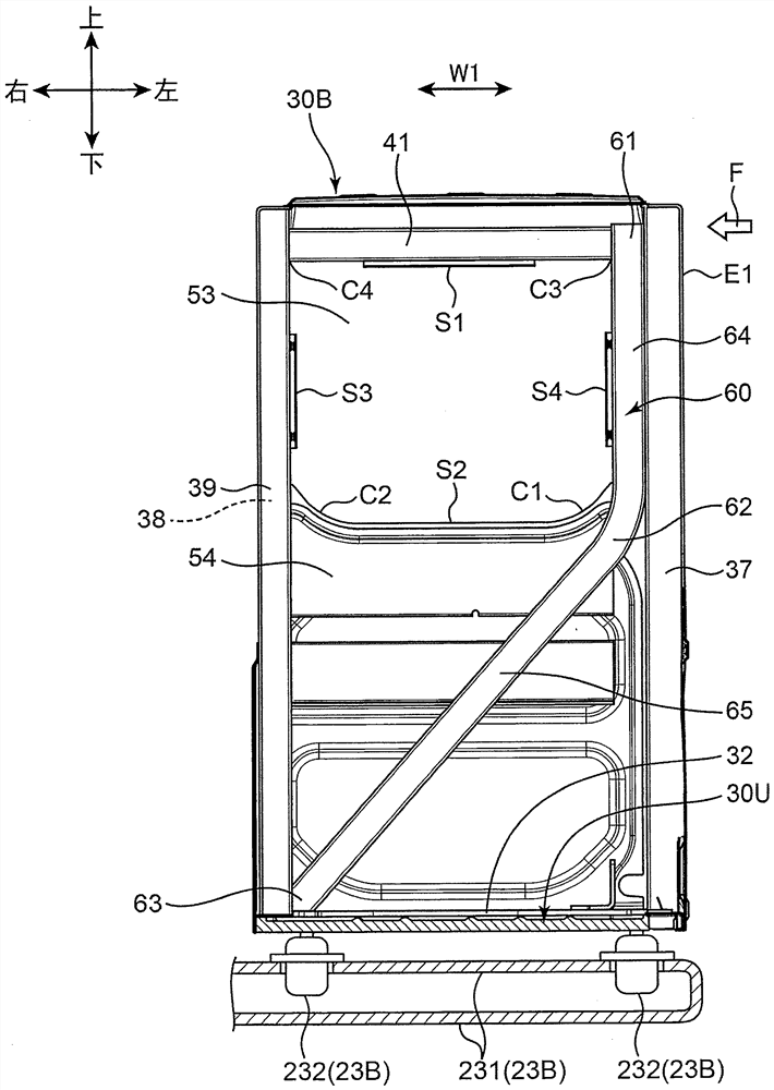
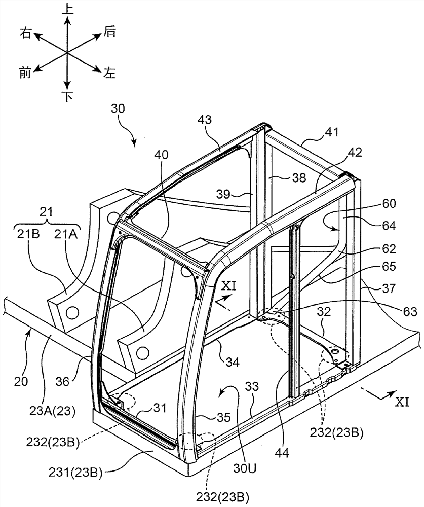
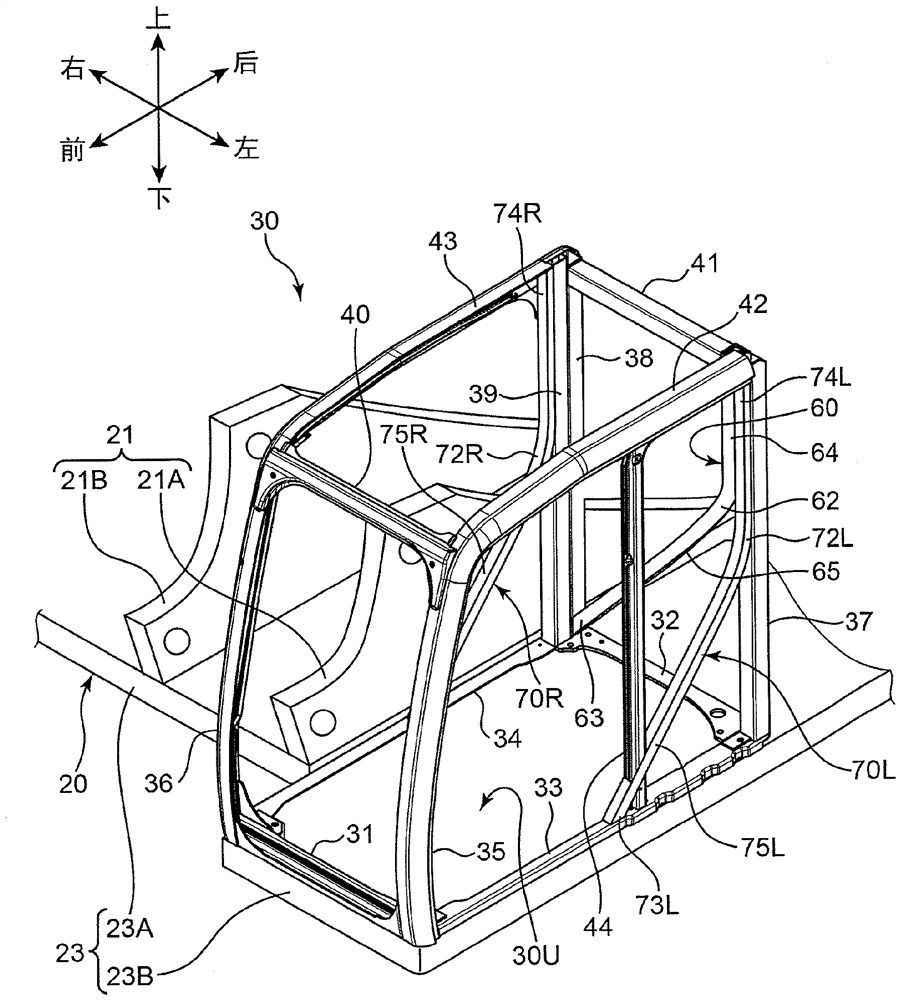
[0098] Figure 17 It is a perspective view showing part of a cab 30 and an upper frame 20 of a hydraulic excavator 10 according to the second embodiment. Figure 18 It is a side view showing the right wall portion 30R of the cab 30 and the load transmission member 70R. Figure 19 is a perspective view showing the left wall portion 30L of the cab 30 and the load transmission member 70L, Figure 20 It is a side view showing the left wall portion 30L and the load transmission member 70L.

[0099] The hydraulic excavator 10 according to the second embodiment is different from the fact that the cab 30 includes the load transmission members 70R and 70L. Figure 1 to Figure 6The hydraulic excavator 10 according to the first embodiment shown is different. Other configurations and Figure 1 to Figure 6 The above-mentioned first embodiment shown is the same.

[0100] like Figure 18 As shown, the right wall portion 30R is located on the right side of the interior space, and is pro...


PUM


Abstract

A load transmission member (60) of a construction machine (10) according to the present invention is provided with: an upper column section (64); an intermediate section (62) extending from a position above a lower corner section (C1) of a window edge of the window (53) and outside in the wall width direction (W1) to a position below the lower corner section (C1) and inside in the wall width direction (W1) so as to avoid the window (53); and a beam portion (65) extending below the window (53) so as to be away from the wall portion side edge (E1). The upper column portion, the intermediate portion, and the beam portion are contiguous in this order so as to be able to transmit a load (F) applied to the upper portion of the cab (30) to the upper frame, and at least the intermediate portion of the load transmission member is formed of a single member. As a result, even when a load is applied to the upper part of the cab, it is possible to suppress the occurrence of breakage at a corner-near portion, which is a portion near the lower corner portion of the window edge of the window, thereby suppressing a decrease in the rigidity of the cab.

Description

technical field [0001] The present invention relates to engineering machinery. Background technique [0002] A hydraulic excavator as an example of a construction machine includes: a lower traveling body; an upper frame rotatably supported by the lower traveling body; a working device including a boom supported up and down by the upper frame; The inner space is composed of a box, and is supported by the upper frame on the side of the boom. The cab includes a plurality of wall portions that surround the interior space in front, rear, and left and right. The plurality of wall portions include, for example, a rear wall portion forming the rear surface of the cab, a left wall portion and a right wall portion forming the left side surface and the right side surface of the cab, and the like. The rear wall part may have a window edge defining a rear window, and each of the left wall part and the right wall part may have a window edge defining a side window. The rear window and s...

Claims


Application Information

Patent Timeline
Patent Type & Authority Applications(China)
IPC IPC(8): E02F3/28E02F3/36E02F3/40E02F3/42E02F9/16E02F9/08
CPCE02F9/163B62D33/0617B62D27/023
Inventor 山本启二下井卓三松岛慎之介
Owner KOBELCO CONSTR MASCH CO LTD
Why Eureka
Try Eureka