
Retarder oil supply method and retarder oil supply system

An oil supply system and retarder technology are applied in the fields of retarder oil supply method and retarder oil supply system, and can solve the problems of retarder braking force drop, large braking force pulsation, insufficient braking force and the like

Pending Publication Date: 2022-04-12
FAWER AUTOMOTIVE PARTS
View PDF14 Cites 0 Cited by
  • Summary
  • Abstract
  • Description
  • Claims
  • Application Information

AI Technical Summary

Problems solved by technology

The existing oil supply method for the retarder is generally to control the height of the oil in the oil storage chamber through compressed air to supply oil to the retarder. However, the height of the oil is controlled by compressed air so that the oil Inevitably, there is an indeterminate amount of gas, and the volume of the gas cannot be controlled. When the retarder is supplied with oil, the braking force of the retarder will decrease, which will lead to insufficient braking force and large pulsation of the braking force.

Method used


Image

  • Retarder oil supply method and retarder oil supply system
  • Retarder oil supply method and retarder oil supply system
  • Retarder oil supply method and retarder oil supply system

Examples


Embodiment Construction

[0022] The following detailed description is provided to assist the reader in gaining an overall understanding of the methods, devices and / or systems described herein. However, various changes, modifications, and equivalents of the methods, apparatus, and / or systems described herein will be apparent upon understanding the disclosure of the present application. For example, the order of operations described herein is an example only and is not limited to the order set forth herein, but, except for operations that must occur in a particular order, can be made that will be apparent after understanding the disclosure of this application. change. Furthermore, descriptions of features that are known in the art may be omitted for increased clarity and conciseness.

[0023] The features described herein may be implemented in different forms and should not be construed as limited to the examples described herein. Rather, the examples described herein have been provided merely to illu...


PUM


Abstract

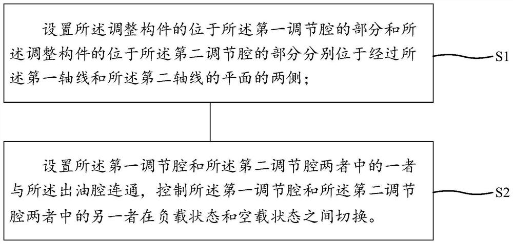
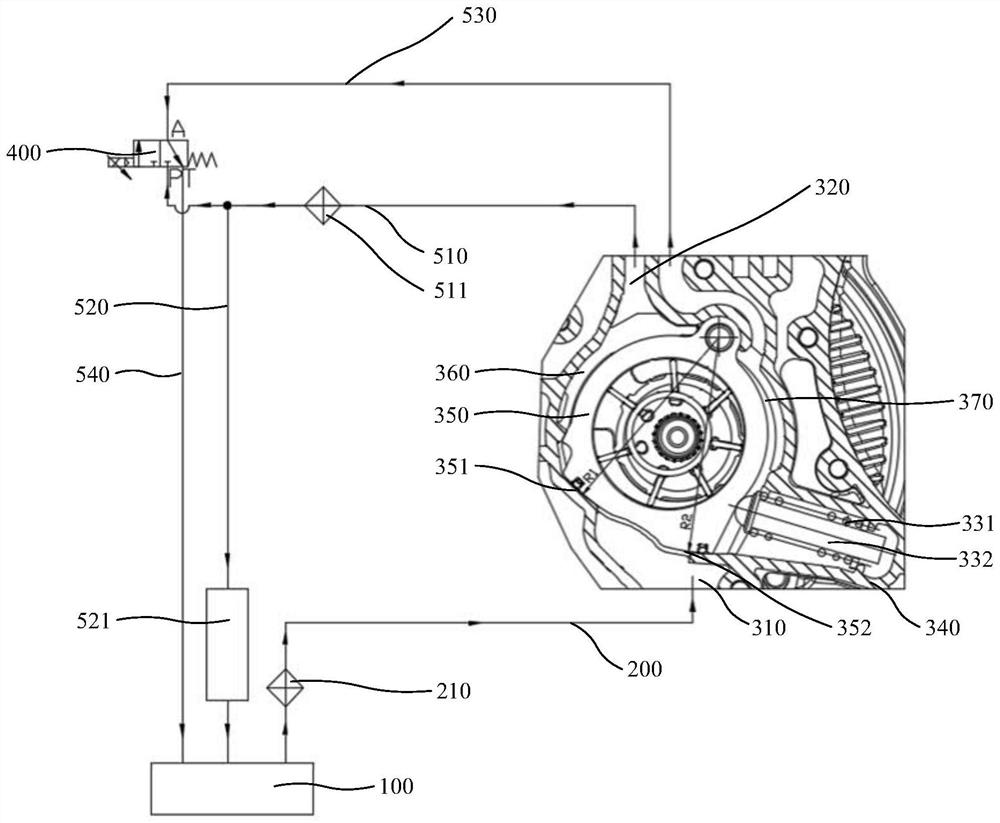
The invention provides a retarder oil supply method and a retarder oil supply system, and relates to the technical field of retarders. The retarder oil supply method comprises the steps that the part, located in the first adjusting cavity, of the adjusting component and the part, located in the second adjusting cavity, of the adjusting component are arranged to be located on the two sides of the plane passing through the first axis and the second axis correspondingly; one of the first adjusting cavity and the second adjusting cavity is arranged to be communicated with the oil outlet cavity, and the other one of the first adjusting cavity and the second adjusting cavity is controlled to be switched between a load state and a no-load state. According to the oil supply method and the oil supply system for the retarder, the problem that when oil is supplied to the retarder in a compressed air mode in an existing oil supply method for the retarder, the braking force is reduced, and then the braking force is insufficient is solved, the oil supply method for the retarder can stably supply oil to the retarder, and the oil supply efficiency of the retarder is improved. And the output curve of the retarder is more stable.

Description

technical field [0001] The present application relates to the technical field of retarders, in particular to a retarder oil supply method and a retarder oil supply system. Background technique [0002] When the retarder uses the principle of the mixed-flow pump to brake, the transmission system drives the retarder rotor to rotate, converting the kinetic energy of the vehicle into the kinetic energy of the medium, which circulates in the blade-type stator and rotor cavity, and the impact and friction convert the kinetic energy of the medium into heat energy of the medium. to generate braking force. The existing oil supply method for the retarder is generally to control the height of the oil in the oil storage chamber through compressed air to supply oil to the retarder. However, the height of the oil is controlled by compressed air so that the oil Inevitably, there is an indeterminate amount of gas in the engine, and the volume of the gas cannot be controlled. When the retar...

Claims


Application Information

Patent Timeline
IPC IPC(8): F16D57/02F16D65/00F17D1/14F17D3/01F16D125/16
CPCY02T10/64
Inventor 王彤高志峥黄飞王欠欠
Owner FAWER AUTOMOTIVE PARTS
Learn More