Brake device

A technology of braking device and brake pedal, which is applied to foot start device, bicycle brake, bicycle accessories, etc., can solve the problems of vehicle braking performance safety defects, inability to brake performance, inapplicability, etc. The effect of improved application, practicality and safety factor, and low manufacturing cost

Pending Publication Date: 2022-07-29
韩青山
View PDF0 Cites 0 Cited by
  • Summary
  • Abstract
  • Description
  • Claims
  • Application Information

AI Technical Summary

Problems solved by technology

[0006] No matter which of the above braking methods, although the vehicle braking function is realized, the braking performance of the tricycle with a load of more than 1 ton is far from comparable to other standardized motor vehicles, and the vehicle braking performance has serious safety defects.
The most important reason: the three-wheeled motorcycle engine cannot drive the vacuum negative pressure brake booster system, and many vehicles cannot apply the vacuum negative pressure brake booster system due to factors such as installation space and high cost

Method used


Image

  • Brake device
  • Brake device
  • Brake device

Examples


Embodiment 1

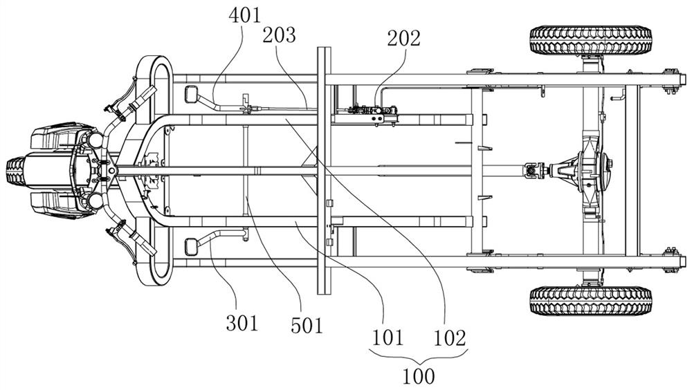
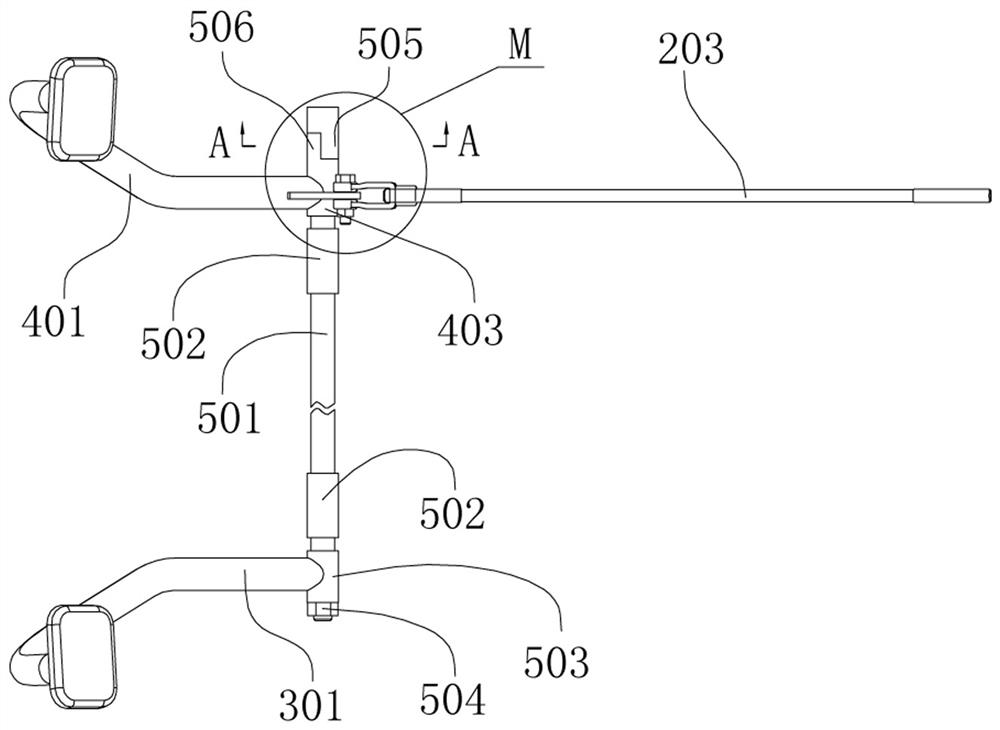
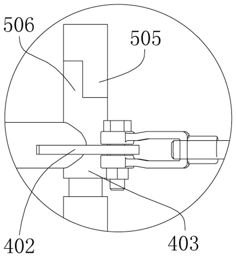
[0085] Example 1: see Figure 1-Figure 4 , the linkage mechanism of the present application includes a linkage shaft 501, and the linkage shaft 501 is rotatably connected to the frame assembly through a fixed sleeve 502. As shown in the figure, the application is provided with two fixed sleeves 502 on the linkage shaft 501, two The fixing sleeves 502 are respectively fixed on the right frame 102 and the left frame 101. The lower end of the right brake pedal 401 is fixedly connected with a right pedal sleeve 403 and is rotatably sleeved on the linkage shaft 501 through the right pedal sleeve 403. The right pedal sleeve 403 is also provided with a right pedal swing arm 402, the first end of the brake link mechanism 203 is connected with the right pedal swing arm 402, and the second end of the brake link mechanism 203 Connect to the brake. In this embodiment, by stepping on the right pedal, the right brake pedal 401, the right pedal sleeve 403 and the right pedal swing arm 402 a...

Embodiment 2

[0090] Example 2, see Figure 5 As shown: the structure in this embodiment is basically the same as that in the first embodiment, the difference lies in that the setting position of the clutch mechanism is different, the clutch mechanism in the first embodiment is arranged between the right brake pedal 401 and the linkage shaft 501, The clutch mechanism in this embodiment is arranged between the left brake pedal 301 and the linkage shaft 501; in this embodiment, the lower end of the left brake pedal 301 is fixedly connected with a left coupling sleeve 4031 and passes through the left coupling sleeve 4031 is rotatably sleeved on the left end of the linkage shaft 501, the lower end of the right brake pedal 401 is provided with a spline sleeve 503 and is meshed with the spline sleeve 503 on the right end of the linkage shaft 501 and then fastened by a nut , so that the right brake pedal 401 rotates synchronously with the linkage shaft 501, the spline sleeve 503 is also provided w...

Embodiment 3

[0092] Example 3: see Figure 6-10 , the frame assembly of the present application is provided with a right pedal shaft 404 and a left pedal shaft 304 . Specifically: the right pedal shaft 404 is arranged on the right frame 102, the left pedal shaft 304 is arranged on the left frame 101, the lower end of the right brake pedal 401 is provided with a right pedal sleeve 403 and passes through the right pedal The sleeve 403 is rotatably sleeved on the right pedal shaft 404, and a right pedal swing arm 402 is also provided on the right pedal sleeve 403; the lower end of the left brake pedal 301 is provided with a left pedal The rod sleeve 303 is rotatably sleeved on the left pedal shaft 304 through the left pedal sleeve 303, and a left pedal swing arm 302 is also provided on the left pedal sleeve 303;

[0093] The linkage mechanism of this embodiment includes a brake shaft 601, two sides of the brake shaft 601 are respectively fitted into the holes at one end of the two support sl...


PUM


Abstract

The invention belongs to the field of motor vehicle brake systems. The braking device comprises a frame assembly, a right braking foot bar arranged on the frame assembly and a brake used for driving braking, the right braking foot bar and the brake are connected through a braking connecting rod mechanism, the braking device further comprises a left braking foot bar arranged on the frame assembly, and a linkage mechanism is arranged between the left braking foot bar and the braking connecting rod mechanism; the linkage mechanism is used for realizing the driving action of the left brake foot bar on the brake connecting rod mechanism; a clutch mechanism is arranged between the left brake foot bar and the brake connecting rod mechanism; when the right brake foot bar actively brakes, the clutch mechanism can achieve linkage separation and combination between the left brake foot bar and the brake connecting rod mechanism within a certain range. The vacuum negative-pressure braking boosting system is simple in structure, reasonable in design and low in cost, can effectively achieve the braking boosting function without depending on the vacuum negative-pressure braking boosting system during working, and is safe and reliable.

Description

technical field [0001] The invention belongs to the field of motor vehicle braking systems, in particular to a braking device. Background technique [0002] With the development of three-wheeled motorcycles, the load capacity of the whole vehicle is constantly increasing. The most important safety factor for the improvement of the vehicle's own weight and load is to improve the braking performance, especially in hilly and mountainous areas, due to the large road slope, good braking performance is more important. At present, in the domestic and foreign markets, the load capacity of many motorized three-wheeled motorcycles exceeds 1 ton, and even reaches 2-3 tons. The braking performance of their three-wheeled motorcycles can no longer meet the needs of users. [0003] The brake systems of the current three-wheeled motorcycles all use mechanical lever drum rear brakes and hydraulic rear brakes driven by mechanical levers. . No matter what kind of braking method, it mainly r...

Claims


Application Information

Patent Timeline
Patent Type & Authority Applications(China)
IPC IPC(8): B60T7/06B62L3/04
CPCB60T7/06B62L3/04
Inventor 韩青山
Owner 韩青山
Why Eureka
Try Eureka