
Transmission mechanism of oral irrigator

A technology of transmission mechanism and punching device, which is applied to transmission parts, electromechanical devices, mechanical equipment, etc., can solve the problems of shortening the service life of the meshing gear punching device, unable to adjust the meshing gear gap, and meshing gear meshing gear wear and other problems. Achieve the effect of eliminating assembly tolerances, extending service life, and uniform gaps

Pending Publication Date: 2022-04-12
SHENZHEN FORTUNECOME TECH CO LTD
View PDF0 Cites 0 Cited by
  • Summary
  • Abstract
  • Description
  • Claims
  • Application Information

AI Technical Summary

Problems solved by technology

[0003] Due to the assembly and positioning of the two parts of the current transmission mechanism of the dental flosser on the market, the gap between the meshing gears in the transmission mechanism is uneven, and the existing transmission mechanism cannot adjust the gap between the meshing gears. The noise, the uneven clearance of the meshing gears will also cause greater wear to the meshing gears, shortening the service life of the two meshing gears and the overall dental flosser

Method used


Image

  • Transmission mechanism of oral irrigator
  • Transmission mechanism of oral irrigator
  • Transmission mechanism of oral irrigator

Examples


Embodiment 1

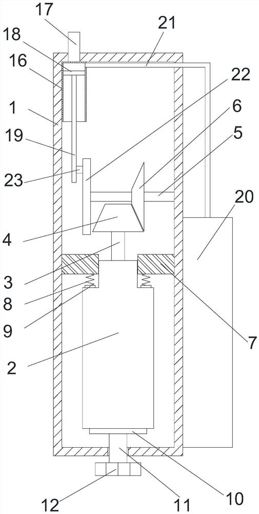
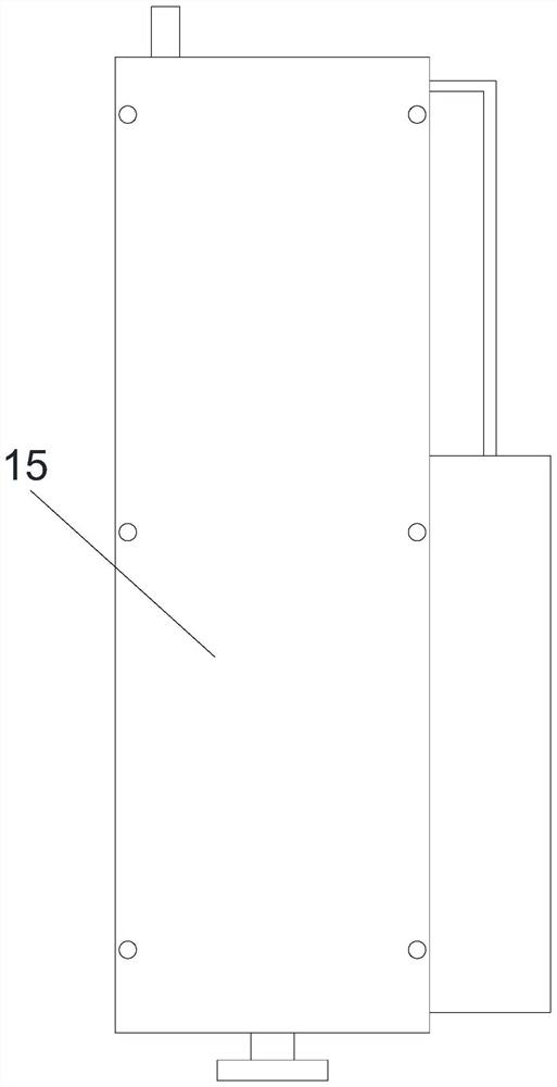
[0051] The embodiment of the present invention provides a dental flosser transmission mechanism, such as Figure 1-5 As shown, it includes: a housing 1, a motor 2 is arranged in the housing 1, a first rotating shaft 3 is arranged at the output end of the motor 2, a first bevel gear 4 is arranged on the first rotating shaft 3, and a first bevel gear 4 is arranged on the first bevel gear. A second rotating shaft 5 is arranged above the gear 4, and one end of the second rotating shaft 5 is rotationally connected with the inner wall of the housing 1, and a second bevel gear 6 is arranged on the second rotating shaft 5, and the second bevel gear 6 is connected to the inner wall of the housing 1. The first bevel gear 4 is meshed, and an adjustment assembly is also arranged in the housing 1 , and the adjustment assembly is used to adjust the position of the motor 2 .

[0052] The working principle and beneficial effects of the above technical solution are as follows: in the present i...

Embodiment 2

[0054] On the basis of above-mentioned embodiment 1, as figure 1 As shown, the adjustment assembly includes:

[0055] Two guide plates 7, the two guide plates 7 are symmetrically arranged on the left and right sides of the output end of the motor 2, one side of the guide plate 7 is fixedly connected to the inner wall of the housing 1, and the other side of the guide plate 7 The side is slidingly connected with the outer wall of the output end of the motor 2;

[0056] The first spring 8, the first spring 8 is arranged between the guide plate 7 and the motor 2, one end of the first spring 8 is fixedly connected with the bottom wall of the guide plate 7, the first spring 8 The other end extends above the motor 2 and is provided with a pressing plate 9, the bottom wall of the pressing plate 9 abuts against the outer wall of the upper end of the motor 2;

[0057] A support plate 10, the support plate 10 is arranged on the lower surface of the motor 2, and the upper surface of the...

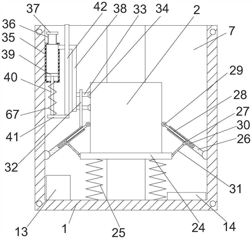
Embodiment 3

[0062] On the basis of embodiment 1 or 2, such as figure 2 As shown, the housing 1 is also provided with a power supply 13 and a first controller 14, the power supply 13 is electrically connected to the motor 2, and the first controller 14 is connected to the power supply 13 and the motor 2 respectively. 2 electrical connection.

[0063] The working principle and beneficial effects of the above technical solution are: the housing 1 is provided with a power source 13 and a first controller 14, the power source 13 can supply power to the motor 2 and the first controller 14, and the first controller 14 can control the motor 2 to work.


PUM


Abstract

The invention provides an oral irrigator transmission mechanism which comprises a shell, a motor is arranged in the shell, a first rotating shaft is arranged at the output end of the motor, a first bevel gear is arranged on the first rotating shaft, a second rotating shaft is arranged above the first bevel gear, one end of the second rotating shaft is rotationally connected with the inner wall of the shell, and the other end of the second rotating shaft is rotationally connected with the inner wall of the shell. A first bevel gear is arranged on the first rotating shaft, a second bevel gear is arranged on the second rotating shaft, the second bevel gear is meshed with the first bevel gear, and an adjusting assembly is further arranged in the shell and used for adjusting the position of the motor. The first rotating shaft and the second rotating shaft are both installed in the shell, the assembly tolerance is eliminated, the position of the motor can be adjusted through the adjusting assembly, and therefore the gap between the first bevel gear and the second bevel gear is adjusted, the gap between the first bevel gear and the second bevel gear is made to be uniform, and noise generated when the first bevel gear and the second bevel gear are in meshing transmission is reduced; the abrasion of the first bevel gear and the second bevel gear is reduced, and the service life of the oral irrigator is prolonged.

Description

technical field [0001] The invention relates to the technical field of dental flossers, in particular to a transmission mechanism of a dental flosser. Background technique [0002] The dental flosser pressurizes the water through the pump body, which can generate 800-1600 ultra-fine high-pressure pulsed water columns per minute, just like the high-pressure water gun can easily clean the car, relying on the impact of its own water flow to reach the teeth Cleaning effect. The flosser can remove food residue and harmful bacteria accumulated in the gaps between the teeth and the teeth where the floss cannot reach, effectively preventing tooth decay. [0003] Due to the assembly and positioning of the two parts of the current transmission mechanism of the dental flosser on the market, the gap between the meshing gears in the transmission mechanism is uneven, and the existing transmission mechanism cannot adjust the gap between the meshing gears. The noise, the uneven clearance ...

Claims


Application Information

Patent Timeline
Patent Type & Authority Applications(China)
IPC IPC(8): F16H57/12F16H57/04H02K7/116H02K5/26A61C17/028
Inventor 方晓林
Owner SHENZHEN FORTUNECOME TECH CO LTD
Learn More