Supercharge Your Innovation With Domain-Expert AI Agents!

Electric actuator

A technology of electric actuator and rotation sensor, which is applied to electric components, transmission boxes, electromechanical devices, etc., can solve the problems of increasing working hours and time, and achieve the effect of reducing working hours and time.

Pending Publication Date: 2022-04-12
NIDEC TOSOK CORP
View PDF7 Cites 0 Cited by
  • Summary
  • Abstract
  • Description
  • Claims
  • Application Information

AI Technical Summary

Problems solved by technology

In this case, in the structure where the motor shaft and the output shaft are arranged on the same shaft, the first rotation sensor and the second rotation sensor need to be arranged on different sides of the axial direction, so there is a need to assemble the first rotation sensor and the second rotation sensor. The problem of increased man-hours and time required for the work of the rotation sensor

Method used


Image

  • Electric actuator
  • Electric actuator

Examples


Embodiment Construction

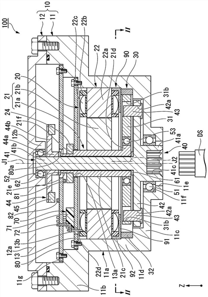
[0012] In each figure, the Z-axis direction is a vertical direction in which the positive side (+Z side) is the upper side and the negative side (−Z side) is the lower side. The axial direction of the motor axis J1 appropriately shown in each figure is parallel to the Z-axis direction, that is, the vertical direction. In the following description, the direction parallel to the axial direction of the motor axis J1 is simply referred to as "axial direction". In addition, the radial direction centered on the motor axis J1 is simply referred to as "radial direction", and the circumferential direction centered on the motor axis J1 is simply referred to as "circumferential direction".

[0013] In this embodiment, the lower side corresponds to "one side in the axial direction", and the upper side corresponds to "the other side in the axial direction". In addition, the up-down direction, upper side, and lower side are only names for describing the relative positional relationship of ...


PUM


Abstract

An electric actuator is provided with: a motor having a motor shaft and a rotor body; a transmission mechanism connected to one side of the motor shaft in the axial direction; an output shaft extending in the axial direction of the motor shaft, the rotation of the motor shaft being transmitted to the output shaft via a transmission mechanism; a first rotation sensor capable of detecting rotation of the motor shaft; and a second rotation sensor capable of detecting rotation of the output shaft. The motor shaft is a hollow shaft. The output shaft passes through the interior of the motor shaft from a position closer to one side in the axial direction than the motor shaft and extends to a position closer to the other side in the axial direction than the motor shaft. A portion of the motor shaft located on the other side in the axial direction than the rotor main body is provided with a first detected portion in which rotation is detected by the first rotation sensor. A portion of the output shaft located further toward the other side in the axial direction than the motor shaft is provided with a second portion to be detected in which rotation is detected by a second rotation sensor.

Description

technical field [0001] The present invention relates to electric actuators. Background technique [0002] There is known an electric actuator including a motor shaft and an output shaft connected by a transmission mechanism. For example, Patent Document 1 describes a rotary actuator applied as a power source of a shift-by-wire system for switching gears of an automatic transmission of a vehicle. [0003] Patent Document 1: Japanese Patent Laid-Open No. 2016-109226 [0004] In an electric actuator as described above, a first rotation sensor capable of detecting the rotation of the motor shaft and a second rotation sensor capable of detecting the rotation of the output shaft may be provided. In this case, in the structure in which the motor shaft and the output shaft are arranged on the same shaft, the first rotation sensor and the second rotation sensor need to be arranged on different sides of the axial direction, so there is a need to assemble the first rotation sensor an...

Claims


Application Information

Patent Timeline
IPC IPC(8): F16H61/32F16H63/40F16H57/02H02K7/00H02K7/116H02K11/215G01D5/12G01D5/14
Inventor 白井宽加藤瞬
Owner NIDEC TOSOK CORP
Features
  • R&D
  • Intellectual Property
  • Life Sciences
  • Materials
  • Tech Scout
  • Unparalleled Data Quality
  • Higher Quality Content
  • 60% Fewer Hallucinations
Learn More