Bidirectional hard sealing rotary ball valve

A technology of rotary ball valve and hard seal, which is applied in the field of two-way hard-sealed rotary ball valve, which can solve the problems of high contact pressure between the valve plate and the floating valve seat, increasing the opening and closing torque of the valve, and affecting the life of the sealing pair, etc.

Pending Publication Date: 2022-04-12
HUNAN PUMP VALVE MFG CO LTD
View PDF0 Cites 0 Cited by
  • Summary
  • Abstract
  • Description
  • Claims
  • Application Information

AI Technical Summary

Problems solved by technology

[0002] The existing rotary ball valve adopts the technology of setting a floating valve seat on the valve body, so that when the valve shaft and the valve plate are elastically deformed after being subjected to reverse pressure, the floating valve seat will also be slightly displaced under the reverse medium pressure, maintaining contact and seal with the valve plate; however, in the case of forward flow, the valve shaft and the valve plate are also elastically deformed, but there is no displacement space for the floating valve seat in this direction, which will cause the contact pressure between the valve plate and the floating valve seat If it is too large, it will affect the life of the sealing pair and greatly increase the opening and closing torque of the valve

Method used


Image

  • Bidirectional hard sealing rotary ball valve
  • Bidirectional hard sealing rotary ball valve
  • Bidirectional hard sealing rotary ball valve

Examples


Embodiment Construction

[0028] Embodiments of the present invention are described in detail below, examples of which are shown in the drawings, wherein the same or similar reference numerals designate the same or similar elements or elements having the same or similar functions throughout. The embodiments described below by referring to the figures are exemplary only for explaining the present invention and should not be construed as limiting the present invention.

[0029] In describing the present invention, it should be understood that the terms "center", "longitudinal", "transverse", "length", "width", "thickness", "upper", "lower", "front", " Rear", "Left", "Right", "Vertical", "Horizontal", "Top", "Bottom", "Inner", "Outer", "Axial", "Radial", "Circumferential" The orientation or positional relationship indicated by etc. is based on the orientation or positional relationship shown in the drawings, and is only for the convenience of describing the present invention and simplifying the descriptio...


PUM


Abstract

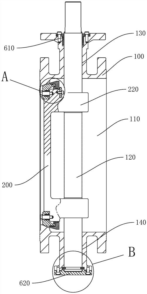
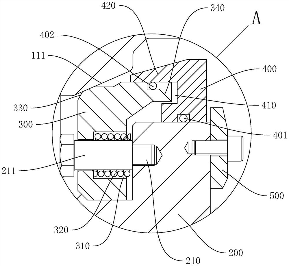
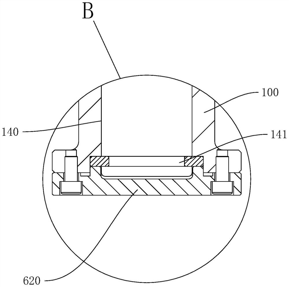
The invention discloses a two-way hard sealing rotary ball valve which comprises a valve body, a valve seat is arranged in the valve body, and a valve shaft capable of rotating around the axis of the valve shaft is arranged in the valve body in a penetrating mode; the valve plate is arranged on the valve shaft in a sleeving mode, and the valve shaft rotates to drive the valve plate to rotate synchronously; the valve plate is provided with a floating valve element, a floating ring and a limiting block, the floating valve element can be connected with the valve seat in a sealed mode to control the valve body to be closed, the floating ring can abut against the floating valve element to improve the sealing pressure of the floating valve element and the valve seat, and the limiting block is used for conducting sliding limiting on the floating ring. And the sealing structure is mounted on the valve body and used for sealing the joint of the valve shaft and the valve body. According to the two-way hard sealing rotary ball valve, the friction force of the sealing face can be effectively reduced, the opening and closing torque of the valve is reduced so as to prolong the service life of equipment, meanwhile, the valve structure is simplified, the valve body and a valve body of a conventional one-way butterfly valve can be commonly used, and the production, manufacturing and maintenance cost is reduced.

Description

technical field [0001] The invention relates to the technical field related to butterfly valves, in particular to a two-way hard-sealed rotary ball valve. Background technique [0002] The existing rotary ball valve adopts the technology of setting a floating valve seat on the valve body, so that when the valve shaft and the valve plate are elastically deformed after being subjected to reverse pressure, the floating valve seat will also be slightly displaced under the reverse medium pressure, maintaining contact and seal with the valve plate; however, in the case of forward flow, the valve shaft and the valve plate are also elastically deformed, but there is no displacement space for the floating valve seat in this direction, which will cause the contact pressure between the valve plate and the floating valve seat If it is too large, it will affect the life of the sealing pair and greatly increase the opening and closing torque of the valve. Contents of the invention [0...

Claims


Application Information

Patent Timeline
Patent Type & Authority Applications(China)
IPC IPC(8): F16K5/06F16K5/08F16K5/20F16K27/06F16K41/02
Inventor 胡杰朱铁强邱荣水陈礼福
Owner HUNAN PUMP VALVE MFG CO LTD
Why Eureka
Try Eureka