Upper through cavity, lower through cavity and through cavity equipment

A cavity-piercing and equipment technology, applied in mechanical equipment, heat exchange equipment, heat preservation, etc., can solve the problems of affecting the operating efficiency of unit equipment, consuming manpower and financial resources, and wafer scrapping, so as to weaken heat transfer and prevent wafer scrapping , the effect of reducing the contact area

Pending Publication Date: 2022-04-12
PIOTECH CO LTD
View PDF0 Cites 0 Cited by
  • Summary
  • Abstract
  • Description
  • Claims
  • Application Information

AI Technical Summary

Problems solved by technology

If the condensed gas remaining on the tube wall reacts with other gases to form particles, as the particles increase, the particles will explode beyond the standard, resulting in wafer scrapping
Wafer scrapping occurs from time to time in actual operations. After discovering that the wafer is scrapping, technicians need to replace all the gas pipelines. This will consume a lot of manpower and financial resources, and will also affect the operating efficiency of the unit equipment.

Method used


Image

  • Upper through cavity, lower through cavity and through cavity equipment
  • Upper through cavity, lower through cavity and through cavity equipment
  • Upper through cavity, lower through cavity and through cavity equipment

Examples


Embodiment Construction

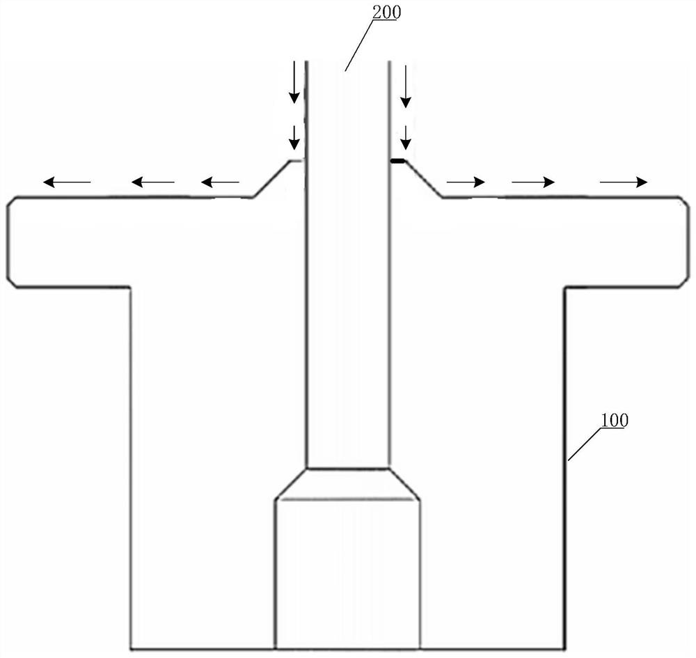
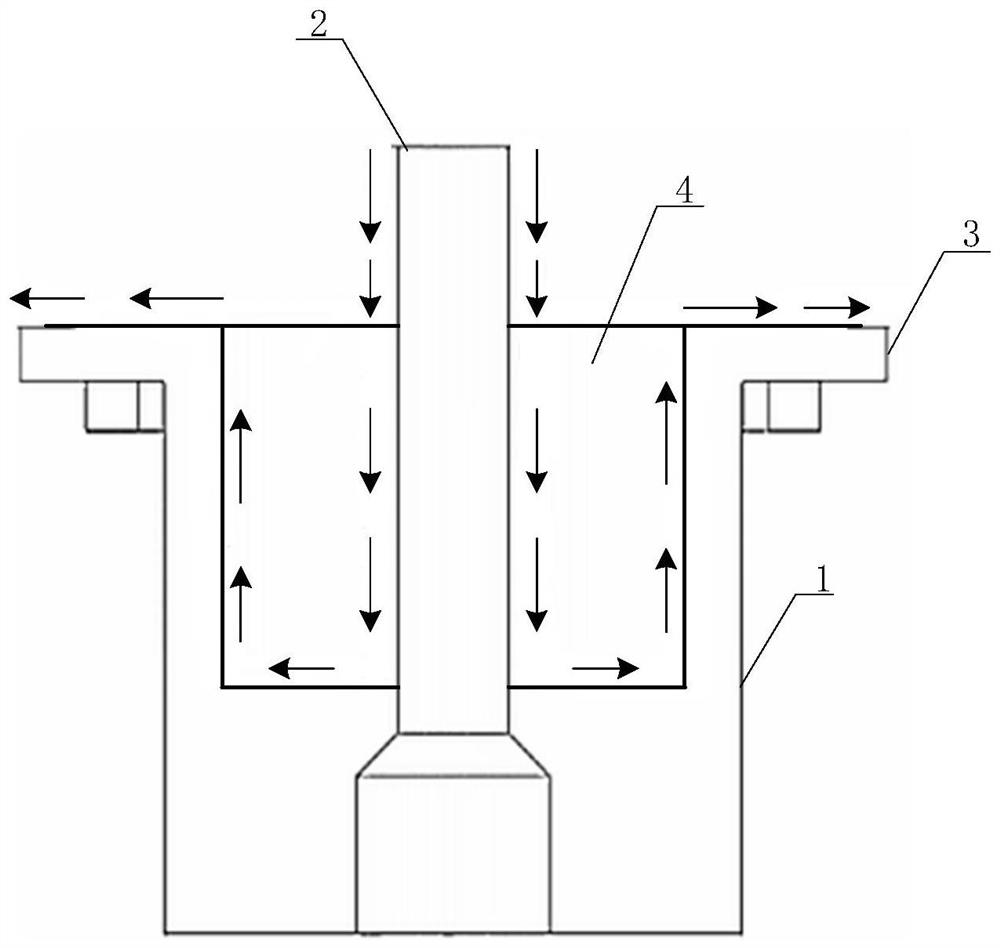
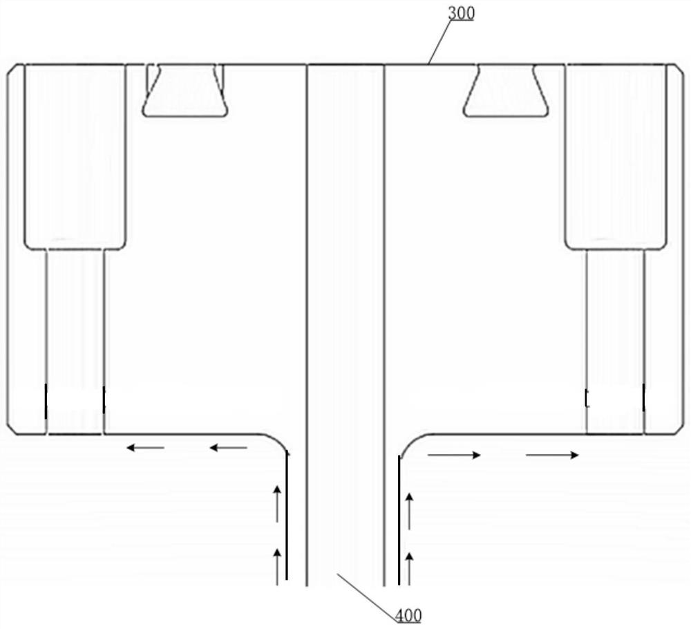
[0027] The invention discloses an upper piercing cavity, which can avoid gas condensation, thereby preventing wafers from being scrapped and replacing gas pipelines. The invention also discloses a lower cavity piercing device and a cavity piercing device.

[0028] The following will clearly and completely describe the technical solutions in the embodiments of the present invention with reference to the accompanying drawings in the embodiments of the present invention. Obviously, the described embodiments are only part of the embodiments of the present invention, not all of them. Based on the embodiments of the present invention, all other embodiments obtained by persons of ordinary skill in the art without making creative efforts fall within the protection scope of the present invention.

[0029] In the description of the present invention, the orientation or positional relationship indicated by the terms "upper", "lower", "top", "bottom" etc. is based on the orientation or po...


PUM


Abstract

The invention discloses an upper penetrating cavity, a lower penetrating cavity and penetrating cavity equipment, the upper penetrating cavity is provided with an upper concave cavity formed by sinking downwards along the top end face of the upper penetrating cavity, and an upper pipeline penetrates through the upper concave cavity and extends into an inner cavity of the upper penetrating cavity; a gap is formed between the part, located in the upper concave cavity, of the upper pipeline and the side wall of the upper concave cavity. By changing the structures of the upper penetrating cavity and the lower penetrating cavity, heat transfer between the upper pipeline and the upper cover plate and between the lower pipeline and the fixing piece is weakened, and meanwhile, a heating source is increased, so that gas condensation is prevented, wafer scrapping is prevented, gas pipeline replacement is avoided, manpower and financial resources are saved, and the production efficiency is improved. And meanwhile, the operation efficiency of unit equipment is improved.

Description

technical field [0001] The invention relates to the field of gas pipelines, and more specifically relates to an upper piercing cavity, a lower piercing cavity and a piercing device. Background technique [0002] The gas pipeline for transporting gas includes piercing equipment, and the piercing equipment mainly includes an upper piercing chamber and a lower piercing chamber. The upper pipeline is threaded into the upper piercing chamber from above the upper piercing chamber, and the lower pipeline is threaded into the lower piercing chamber from below the lower piercing chamber. During normal operation, the upper piercing chamber and the lower piercing chamber are in closed contact, so that the upper pipeline and the lower pipeline are connected. When maintenance is required, the upper piercing chamber is driven to separate from the lower piercing chamber. [0003] When transporting gas, the temperature in the gas pipeline needs to be maintained at a preset temperature val...

Claims


Application Information

Patent Timeline
IPC IPC(8): F16L53/30F16L59/02F16L23/032
Inventor 张建谈太德褚鑫辉刘婧婧李景舒赵婷婷
Owner PIOTECH CO LTD
Why Eureka
Try Eureka