

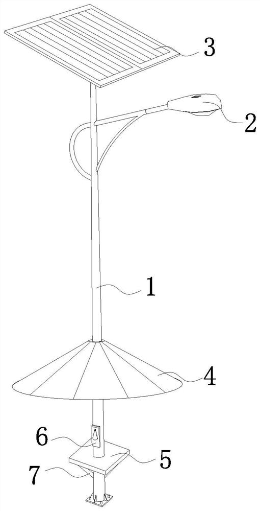
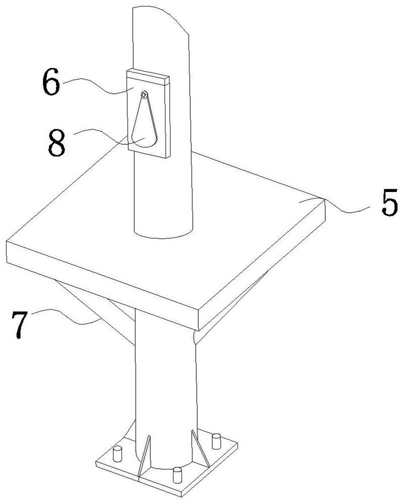
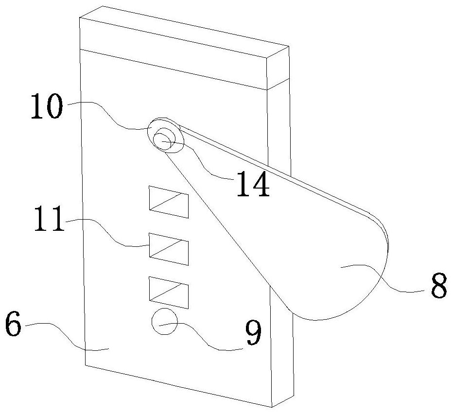
Solar street lamp charging pile
A solar street lamp and charging pile technology, applied in electric light sources, energy-saving lighting, with built-in power supply, etc., can solve the problems of dust entering the charging port, being easily bitten by mosquitoes, and the function of single lighting of solar street lamps, etc., to solve the umbrella shed. Shadows, Increase Lighting Range, Increase Lighting Range effects
- Summary
- Abstract
- Description
- Claims
- Application Information
AI Technical Summary
Problems solved by technology
Method used
Image

Examples
Embodiment Construction
[0032] The following will clearly and completely describe the technical solutions in the embodiments of the present invention with reference to the accompanying drawings in the embodiments of the present invention. Obviously, the described embodiments are only some, not all, embodiments of the present invention. Based on the embodiments of the present invention, all other embodiments obtained by persons of ordinary skill in the art without making creative efforts belong to the protection scope of the present invention.
[0033] In describing the present invention, it is to be understood that the terms "center", "longitudinal", "transverse", "length", "width", "thickness", "upper", "lower", "front", " Back", "Left", "Right", "Straight", "Horizontal", "Top", "Bottom", "Inner", "Outer", "Clockwise", "Counterclockwise", etc. or The positional relationship is based on the orientation or positional relationship shown in the drawings, which is only for the convenience of describing t...
PUM
 Abstract
Description
Claims
Application Information