Distributed optical fiber temperature measurement parameter automatic adjustment system and method

A distributed optical fiber and automatic adjustment technology, applied in thermometers, measuring devices, measuring heat, etc., can solve the problems of inconvenient adjustment parameters, troublesome manual modification, increased fiber loss, etc., to achieve convenient use, convenient operation, and avoid opening and closing The effect of action

Pending Publication Date: 2022-04-12
浙江振东光电科技有限公司
View PDF1 Cites 1 Cited by
  • Summary
  • Abstract
  • Description
  • Claims
  • Application Information

AI Technical Summary

Problems solved by technology

[0005] However, when the optical fiber is used for a certain period of time, the loss of the optical fiber will gradually increase, and the parameters need to be adjusted at this time; in addition, as the temperature changes, the change of the optical fiber loss will also increase. At this time , it is also necessary to adjust the parameters
At present, the method of manually adjusting parameters is adopted, but there are many inconveniences in manual modification, for example, it is not known when to adjust, and temperature changes often occur, so manual modification is very troublesome and time-consuming. It is very inconvenient to adjust the parameters in places where the environment is harsh or it is inconvenient to enter casually.

Method used


Image

  • Distributed optical fiber temperature measurement parameter automatic adjustment system and method
  • Distributed optical fiber temperature measurement parameter automatic adjustment system and method
  • Distributed optical fiber temperature measurement parameter automatic adjustment system and method

Examples


Embodiment Construction

[0046] The present invention will be described in further detail below in conjunction with the accompanying drawings and specific embodiments.

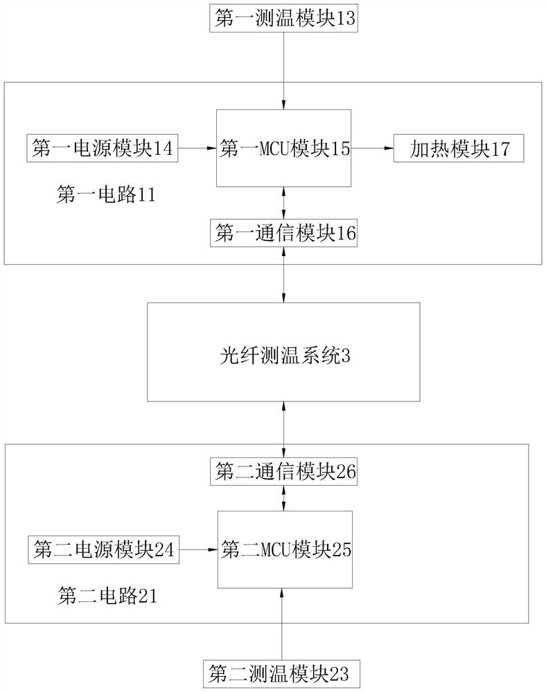
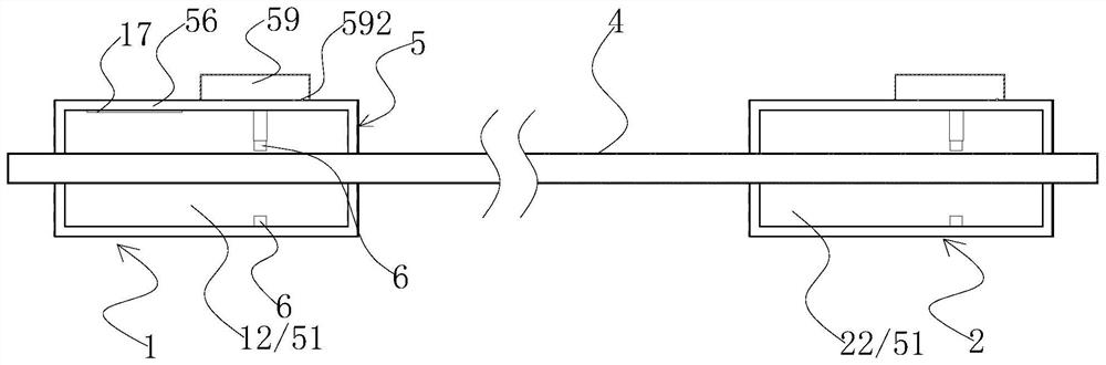
[0047] Such as figure 1 it is good figure 2 As shown, this embodiment provides an automatic adjustment system for distributed optical fiber temperature measurement parameters, including a first temperature measurement device 1 and a second temperature measurement device 2 connected to an optical fiber temperature measurement system 3, the first temperature measurement device 1 and the second temperature measurement device 2 The second temperature measuring device 2 is installed in different positions of the optical fiber 4 respectively, and the first temperature measuring device 1 includes a first circuit 11, a first heat preservation chamber 12 and a first heat preservation chamber 12 that is connected to the first circuit 11. A temperature measurement module 13, the second temperature measurement device 2 includes a second circuit...


PUM


Abstract

The invention provides a distributed optical fiber temperature measurement parameter automatic adjustment system and method, and the system comprises a first temperature measurement device and a second temperature measurement device which are connected to an optical fiber temperature measurement system, and are respectively disposed at different positions of an optical fiber. The first temperature measuring device comprises a first circuit, a first heat preservation cavity and a first temperature measuring module located in the first heat preservation cavity and connected to the first circuit, the second temperature measuring device comprises a second circuit, a second heat preservation cavity and a second temperature measuring module located in the second heat preservation cavity and connected to the second circuit, and the first circuit is used for being in communication connection with an optical fiber temperature measuring system. The second circuit is used for communication connection with an optical fiber temperature measurement system. According to the scheme, parameters can be automatically adjusted at any time, the two temperature measuring devices with the heat preservation cavities are provided and directly arranged on the optical fiber in a sleeving mode in the using process, using is very convenient, winding is not needed, a thermostatic bath is not needed, and the system has the advantages of being convenient to use, high in practicability and the like.

Description

technical field [0001] The invention belongs to the technical field of temperature measurement based on distributed optical fibers, and in particular relates to a system and method for automatically adjusting temperature measurement parameters of distributed optical fibers. Background technique [0002] The working principle of the distributed optical fiber temperature sensor is based on the temperature characteristics of the optical fiber back Raman scattering. Since the temperature information of each point of the optical fiber is represented by Raman scattered light pulse signals with different amplitudes, according to the propagation speed of the light wave in the medium and using OTDR technology, the relative round-trip time of the anti-Stokes scattered light signal in the optical fiber is observed And the magnitude of the amplitude can accurately detect the instant temperature and its changes at all points of the optical fiber. The temperature measurement of the distri...

Claims


Application Information

Patent Timeline
Patent Type & Authority Applications(China)
IPC IPC(8): G01K15/00
Inventor 朱竞锋秦一涛
Owner 浙江振东光电科技有限公司
Why Eureka
Try Eureka