Constant temperature type automatic reaction calorimeter

An automatic reaction and calorimeter technology, which is applied in the field of calorimeter and constant temperature automatic reaction calorimeter, can solve the problems of cumbersome cleaning of combustion residues and deviations, and achieve the goals of improving efficiency, shortening temperature difference, and improving flow activity Effect

Pending Publication Date: 2022-04-12
浙江华颀安全科技有限公司
View PDF0 Cites 0 Cited by
  • Summary
  • Abstract
  • Description
  • Claims
  • Application Information

AI Technical Summary

Problems solved by technology

[0005] The invention provides a constant temperature automatic reaction calorimeter, one of which is to have the function of self-cleaning the oxygen bomb, and to solve the problem of cumbersome manual cleaning of combustion residues; the other purpose is to solve There will be deviations in the temperature at different positions inside the temperature measuring liquid to achieve the effect of improving the accuracy of the calorimetric results

Method used


Image

  • Constant temperature type automatic reaction calorimeter
  • Constant temperature type automatic reaction calorimeter
  • Constant temperature type automatic reaction calorimeter

Examples


Embodiment 1

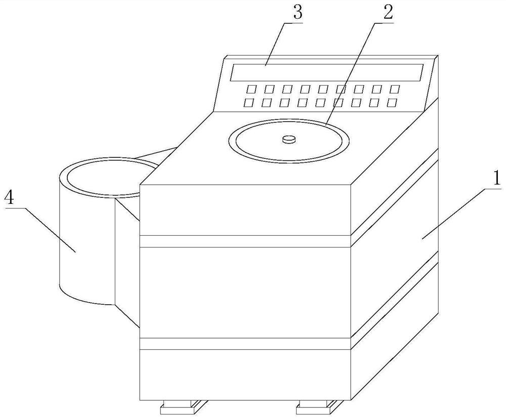
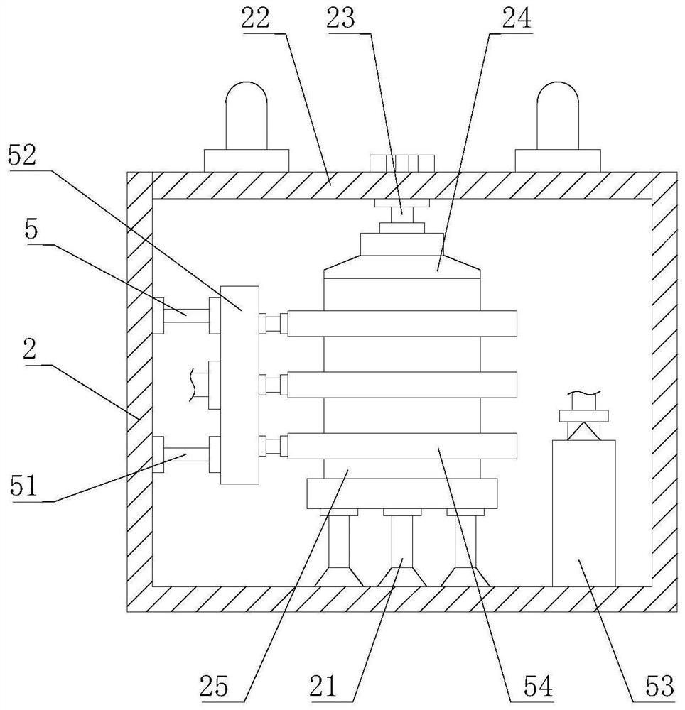
[0033] like Figure 1-7As shown, the present invention provides a constant temperature type automatic reaction calorimeter, comprising a constant temperature type calorimeter body 1, a calorimeter 2 is fixedly installed on the top of the constant temperature type calorimeter body 1, and a constant temperature type calorimeter body 1 A control panel 3 is fixedly installed on the top of the thermostatic calorimeter body 1. A self-cleaning mechanism 4 is provided on the left side of the thermostatic calorimeter body 1. A uniform heating mechanism 5 is provided in the inner cavity of the calorimeter 2. The self-cleaning mechanism 4 includes a self-cleaning cylinder 41 , the self-cleaning cylinder 41 is fixedly installed on the left side of the thermostatic calorimeter body 1, the inner cavity of the self-cleaning cylinder 41 is fixedly installed with a center seat 42, and the top of the center seat 42 is detachably connected to the aerobic bomb body 25, self-cleaning A pump 43 is ...

Embodiment 2

[0035] Such as Figure 1-7 As shown, on the basis of Embodiment 1, the present invention provides a technical solution: preferably, the number of electromagnetic valves 48 is set to two, and the end of the soft water pipe 44 away from the pump 43 is connected to the end of the electromagnetic valve 48 on the left side. The left side is fixedly connected, and the right side of the inner cavity of the self-cleaning cylinder 41 is fixedly equipped with a fan 45, and the air outlet end of the fan 45 is fixedly connected with a heating box 46, and an electric heating wire is arranged in the inner cavity of the heating box 46, and the heating box The bottom of 46 is fixedly connected with an air duct 47, and the end of the air duct 47 away from the heating box 46 is fixedly connected with the right side of the electromagnetic valve 48 located on the right side, and the top of the hollow column 491 extends to the top of the center seat 42 and is fixedly connected with a nozzle Pipe 4...

Embodiment 3

[0037] Such as Figure 1-7 As shown, on the basis of Embodiment 1, the present invention provides a technical solution: preferably, a support plate 4941 is fixedly installed in the inner cavity of the collection cylinder 494, and a centrifugal motor 4942 is fixedly installed at the bottom of the support plate 4941. The output shaft of 4942 extends to the top of the support plate 4941 and is fixedly connected with a connecting cylinder 4943. The top of the connecting cylinder 4943 is rotatably connected with a rotating connecting pipe 4944. The top of the rotating connecting pipe 4944 is fixedly connected with the top of the inner cavity of the collecting cylinder 494. Filter screen 4945 is fixedly installed on the outer wall of 4943, self-closing tube 4946 is fixedly connected on the outer wall of connecting cylinder 4943, and fixed inner frame 4947 is fixedly installed in the inner cavity of self-closing tube 4946, and fixed inner frame 4947 is far away from the connection tub...


PUM


Abstract

The invention discloses a constant-temperature type automatic reaction calorimeter, and relates to the technical field of calorific value measuring devices, the constant-temperature type automatic reaction calorimeter comprises a constant-temperature type calorimeter body, the top of the constant-temperature type calorimeter body is fixedly provided with a calorimetric cylinder, and the top of the constant-temperature type calorimeter body is fixedly provided with a control panel; a self-cleaning mechanism is arranged on the left side of the constant-temperature calorimeter body, and a uniform heating mechanism is arranged in an inner cavity of the calorimetric cylinder. By controlling an electric telescopic rod to stretch and retract repeatedly, sliding of a sliding plate and the design of a first one-way pipe and a second one-way pipe, temperature measuring liquid in a calorimetric cylinder can be absorbed and then conveyed into an inner cavity of a hollow ring through a connecting pipe and a splitter plate, and part of the temperature measuring liquid is sprayed out through the inner wall of an arc-shaped inner pipe; one part of the flow-assisting pipe is fully contacted with the outer wall of the oxygen bomb body, and the other part of the flow-assisting pipe is sprayed out through the outer wall of the flow-assisting pipe, so that the flowing activity of the temperature-measuring liquid is improved, the temperature difference at different positions in the temperature-measuring liquid is shortened, and the accuracy of a calorimetric result is improved.

Description

technical field [0001] The invention relates to a calorimeter, relates to the technical field of calorific value measuring devices, in particular to a constant temperature automatic reaction calorimeter. Background technique [0002] Calorimeter, commonly known as calorimeter, mainly measures the calorific value of coal, straw, petroleum and other solids, and can also measure the calorific value of petroleum and other liquids. It is mainly used in thermoelectricity, cement, coal, new energy and other fields. The heat capacity of the calorimeter is Refers to the heat absorbed by the calorimetry system of the equipment when the temperature increases by 1 °C, expressed in J / K, and the calorific value of the sample is calculated according to the increase of the water temperature after the sample is burned. There are following problems at prior art: [0003] 1. The existing calorimeter does not have the function of self-cleaning the oxygen bomb. After the calorimetry work is com...

Claims


Application Information

Patent Timeline
IPC IPC(8): G01N25/20
Inventor 方明山陈晓张学钰余炜吴雪萍房金秋杨振宇
Owner 浙江华颀安全科技有限公司
Why Eureka
Try Eureka