
Low signal-to-noise ratio inverse synthetic aperture radar imaging method

An inverse synthetic aperture and radar imaging technology, which is applied to instruments, measurement devices, and re-radiation, etc., can solve the problems of estimation result error, reduced image quality, and target image quality degradation, so as to improve efficiency and accuracy, and improve accuracy. degree of effect

Pending Publication Date: 2022-04-12
BEIJING INSTITUTE OF TECHNOLOGYGY
View PDF0 Cites 0 Cited by
  • Summary
  • Abstract
  • Description
  • Claims
  • Application Information

AI Technical Summary

Problems solved by technology

To solve this problem, a low signal-to-noise ratio parameter estimation method based on generalized radon Fourier transform (GRFT) and constant false-alarm rate (CFAR) detection can be used to realize ISAR imaging , but this method still faces a series of problems: the first problem is that the accuracy of parameter estimation is related to the accuracy of GRFT grid division. The image quality is degraded; the second problem is that strong scattering points interfere with the detection of weak scattering points in the CFAR detection process, and the uniformly determined threshold is difficult to remove strong scattering point interference while retaining weak scattering points; third, due to noise In the CFAR detection process, the noise above the threshold must be considered as a real signal, which will lead to inevitable noise in the final ISAR image and reduce the image quality

Method used

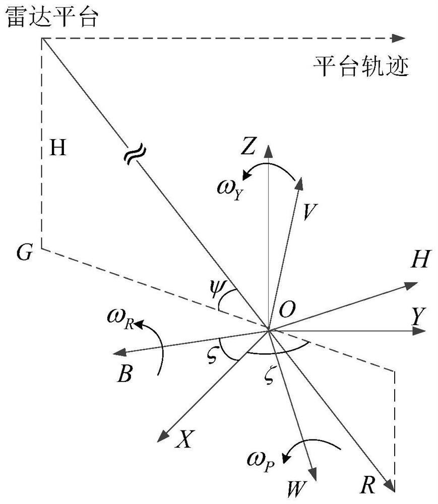

Image

  • Low signal-to-noise ratio inverse synthetic aperture radar imaging method
  • Low signal-to-noise ratio inverse synthetic aperture radar imaging method
  • Low signal-to-noise ratio inverse synthetic aperture radar imaging method

Examples


Embodiment Construction

[0039] The invention provides a low signal-to-noise ratio inverse synthetic aperture radar imaging method, which uses the sidelobe learning particle swarm optimization algorithm SLL-PSO to search in the one-dimensional high-resolution range image, and uses the generalized Radon-Fourier transform GRFT Calculate the amplitude of each particle, and calculate the signal component of the scattering point corresponding to the maximum amplitude; among them, after obtaining the amplitude of multiple particles, select the particle with the largest amplitude as the global optimal particle, and then send to the global On both sides of the optimal particle, a certain number of side lobes are expanded to continue to find the particle with the largest amplitude as the new global optimal particle, and the motion parameters of the scattering points are represented by the position parameters of the new global optimal particle, and the new global optimal particle The amplitude of the optimal parti...


PUM


Abstract

The invention discloses an inverse synthetic aperture radar imaging method with a low signal-to-noise ratio, and the method employs a sidelobe learning particle swarm optimization algorithm and generalized Rawinter-Fourier transform to estimate the amplitude of a scattering point, and avoids the reduction of image quality caused by the conventional grid division. According to the method, a traditional PSO algorithm is improved, after the maximum amplitude in multiple particles is obtained, particles with a certain side lobe number are expanded to the two sides of the particle, the maximum amplitude continues to be found to serve as the amplitude of a scattering point, and the accuracy of final maximum amplitude calculation is improved. The method of removing the signal component of the scattering point corresponding to the maximum amplitude and repeatedly estimating the amplitude of the residual scattering points is adopted to obtain the maximum amplitude of each scattering point and the corresponding motion parameter, so that the problems that the strong scattering point interferes with the detection of the weak scattering point in the traditional constant false alarm rate detection process and the detection accuracy is low due to the existence of noise are solved. And noise points appear in the final ISAR image, and the image quality is reduced.

Description

technical field [0001] The invention relates to the technical field of inverse synthetic aperture radar, in particular to an imaging method for inverse synthetic aperture radar with low signal-to-noise ratio. Background technique [0002] Inverse Synthetic Aperture Radar (ISAR) is an important branch in the development of Synthetic Aperture Radar. ISAR is a high-resolution imaging radar that is different from traditional radars. It can obtain fine images of non-cooperative moving targets, such as aircraft, ships, and missiles, all-weather, all-time, and long-distance. It has important military and civilian values. [0003] ISAR-based moving target imaging technology compensates for the translational component of the target, that is, after removing the consistent motion (translational motion of the target) between the scattering units, and uses the non-uniform motion caused by the shaking of the target to estimate the target The motion parameters of the target are estimated,...

Claims


Application Information

Patent Timeline
Patent Type & Authority Applications(China)
IPC IPC(8): G01S13/90
Inventor 张天意丁泽刚刘书江高永澎龙腾曾涛
Owner BEIJING INSTITUTE OF TECHNOLOGYGY
Learn More