Distributed multimode diffraction imaging method

An imaging method and distributed technology, applied in the field of optical imaging, can solve problems such as restricting common image performance, low diffraction efficiency, and decreased imaging performance, and achieve the effects of improving image resolution, improving diffraction efficiency, and reducing cost

Pending Publication Date: 2022-03-04
HARBIN INST OF TECH
View PDF0 Cites 0 Cited by
  • Summary
  • Abstract
  • Description
  • Claims
  • Application Information

AI Technical Summary

Problems solved by technology

However, the ultra-large-aperture diffraction imaging system needs to design the folding and unfolding structure of the primary mirror. Insufficient splicing accuracy will seriously restrict the common image performance between the apertures. The lower the value is, the lower the imaging performance will be. In addition, the diffraction element also has the problem of wide-spectrum imaging.

Method used


Image

  • Distributed multimode diffraction imaging method
  • Distributed multimode diffraction imaging method
  • Distributed multimode diffraction imaging method

Examples


Embodiment Construction

[0034] The technical solution of the present invention will be further described below in conjunction with the accompanying drawings, but it is not limited thereto. Any modification or equivalent replacement of the technical solution of the present invention without departing from the spirit and scope of the technical solution of the present invention should be covered by the present invention. within the scope of protection.

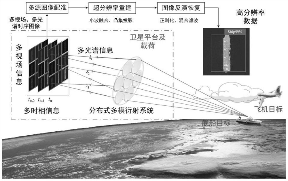
[0035] The invention provides a distributed multimode diffraction imaging method, such as figure 1 As shown, the method includes the following steps:

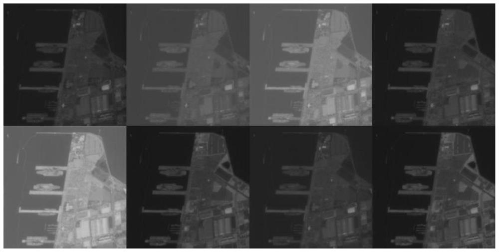
[0036] Step 1: Design a distributed multi-mode diffraction imaging system according to the application requirements to obtain time-series images of multiple fields of view and multiple spectral segments.

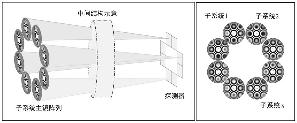
[0037] In this step, the distributed multi-mode diffraction imaging system is composed of several sub-diffraction systems arranged in a distributed manner. Each sub-diffraction system is independently...


PUM


Abstract

The invention discloses a distributed multi-mode diffraction imaging method, which comprises the following steps of: 1, designing a distributed multi-mode diffraction imaging system according to an application requirement, and acquiring a multi-view-field and multi-spectrum time sequence image; step 2, performing registration on the obtained time sequence images with multiple view fields and multiple spectral bands; 3, fusing multi-view-field, multi-spectral-band and multi-temporal information to realize super-resolution reconstruction; and 4, improving an image transfer function by using an image restoration algorithm, and removing background radiation generated by non-design-level diffracted light to obtain a high-resolution image. According to the invention, a plurality of sub-diffraction systems arranged in a distributed manner are used for independent imaging, different detection spectrum segments exist, sub-pixel offset exists among images, after multi-view-field, multi-spectrum and multi-temporal image data are acquired, a high-resolution image is finally acquired through fusion, super-resolution and restoration algorithms, and the method has the advantages of high resolution, light weight, low cost and the like, and is suitable for large-scale popularization and application. And a technical approach is provided for leap-type development of high-resolution optical satellite loads.

Description

technical field [0001] The invention belongs to the field of optical imaging, and relates to an image acquisition method, in particular to an ultra-lightweight, high-resolution, soft-hard combination optical remote sensing image acquisition method. Background technique [0002] High-resolution and high-quality optical satellite remote sensing images can quickly and accurately capture the latest space-time information on the earth's surface and its local areas, and play an important role in environmental monitoring, military reconnaissance, surveying and mapping, monitoring, and warnings. The national military, political and economic significance is self-evident. Due to the particularity of the orbit, high-orbit satellites can achieve continuous observation of key areas of the earth and have high temporal and spatial resolution surveillance capabilities. Theoretically, the resolution of 1-2m in the geostationary orbit needs to be realized through an aperture of more than 10m....

Claims


Application Information

Patent Timeline
IPC IPC(8): G01N23/20G01N23/207
CPCG01N23/20G01N2223/056
Inventor 江世凯胡建明智喜洋张伟董俊廷鲍广震施天俊王达伟
Owner HARBIN INST OF TECH
Why Eureka
Try Eureka