
Resistance compensation circuit and touch display device

A technology of touch display device and compensation circuit, which is applied in the fields of electrical digital data processing, instrumentation, calculation, etc., and can solve problems such as abnormal operation of TDDI chip and data error

Pending Publication Date: 2022-04-12
BEIJING ESWIN COMPUTING TECH CO LTD
View PDF0 Cites 1 Cited by
  • Summary
  • Abstract
  • Description
  • Claims
  • Application Information

AI Technical Summary

Problems solved by technology

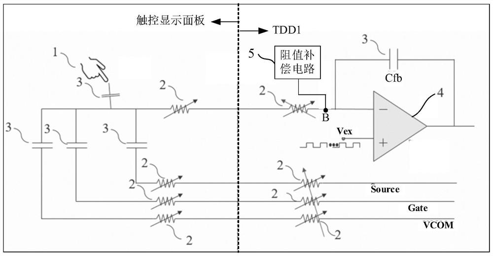
There are a lot of parasitic resistance and parasitic capacitance inside the touch display panel and TDDI chip in the touch display device. When the temperature of the touch display device changes, since the parasitic resistance is more sensitive to the temperature change, the resistance value of the parasitic resistance It will change with the change of temperature, so the resistive load of the sensing module will change, and the Source (source) voltage, Gate (gate) voltage and Sensing (sensing) voltage will generate a voltage difference, so that the internal received TDDI chip Errors occur in the original data, resulting in abnormal internal operation of the TDDI chip

Method used


Image

  • Resistance compensation circuit and touch display device
  • Resistance compensation circuit and touch display device
  • Resistance compensation circuit and touch display device

Examples


Embodiment Construction

[0026] The present application is described in detail below, and examples of embodiments of the present application are shown in the drawings, wherein the same or similar reference numerals represent the same or similar components or components having the same or similar functions throughout. Also, detailed descriptions of known technologies will be omitted if they are not necessary to illustrate the features of the present application. The embodiments described below by referring to the figures are exemplary only for explaining the present application, and are not construed as limiting the present application.

[0027] Those skilled in the art can understand that, unless otherwise defined, all terms (including technical terms and scientific terms) used herein have the same meanings as commonly understood by those of ordinary skill in the art to which this application belongs. It should also be understood that terms, such as those defined in commonly used dictionaries, should ...


PUM


Abstract

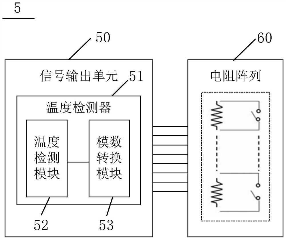
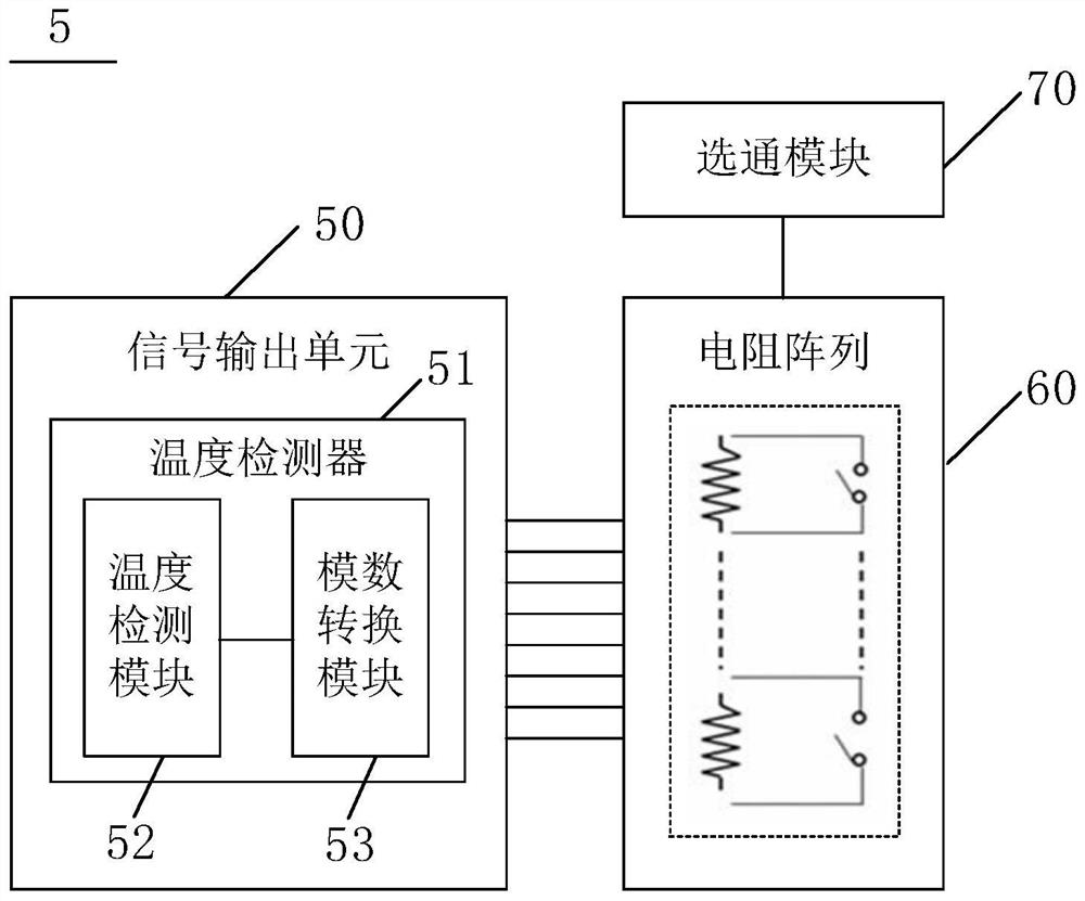
The invention provides a resistance compensation circuit and a touch display device. The resistance compensation circuit is configured to be electrically connected with a sensing module in a touch and display driver integrated chip in the touch display device. The resistance compensation circuit comprises a signal output unit and a resistor array which are electrically connected in sequence. The signal output unit is used for outputting a corresponding switch control signal based on the temperature of the touch display device; the resistor array is used for adjusting the resistance value of the resistor array based on the switch control signal, so that the resistance value variable quantity of the resistor array is equal to the resistance value variable quantity of a parasitic resistor of the touch display device, and the change direction of the resistance value of the resistor array is opposite to the change direction of the resistance value of the parasitic resistor. According to the invention, the resistance value of the resistive load of the sensing module can be kept unchanged, and the normal work of the interior of the touch and display driver integrated chip is ensured.

Description

technical field [0001] The present application relates to the field of display technology, in particular, the present application relates to a resistance compensation circuit and a touch display device. Background technique [0002] With the continuous maturity of screen technology, there are more and more functions and modules on the screen. The requirements for screen touch and display technology are getting higher and higher. [0003] In the prior art, a touch display device includes a touch display panel and a TDDI (Touch and DisplayDriver Integration, touch and display driver integration) chip. When the touch component touches the screen of the touch display panel, the sensing module of the TDDI chip The size of the resistive load is used to judge the touch situation. There are a lot of parasitic resistance and parasitic capacitance inside the touch display panel and TDDI chip in the touch display device. When the temperature of the touch display device changes, since...

Claims


Application Information

Patent Timeline
Patent Type & Authority Applications(China)
IPC IPC(8): G06F3/041G06F3/045
Inventor 林森全栽薰
Owner BEIJING ESWIN COMPUTING TECH CO LTD
Learn More