Electromagnetic relay

A technology of electromagnetic relay and electromagnetic system, applied in the direction of electromagnetic relay, relay, detailed information of electromagnetic relay, etc., can solve the problems of low reliability, short working stroke, small normally closed pressure, etc., reduce assembly complexity and avoid transmission jam hysteresis, eliminating the effect of hinge connections

Pending Publication Date: 2022-04-12
ZHEJIANG CHINT ELECTRIC CO LTD
View PDF0 Cites 0 Cited by
  • Summary
  • Abstract
  • Description
  • Claims
  • Application Information

AI Technical Summary

Problems solved by technology

[0003] At present, most of the transmission indicating mechanisms on the market are assembled structures. The action indicating mechanism is connected with the transmission mechanism by using the principle of leverage. After the product coil is excited, the displacement of the transmission mechanism increases the displacement of one end of the action indicating mechanism, so that the observation window on the top surface of the product Identify the contact position information connected to the transmission mechanism, but there are several disadvantages in this scheme: 1. The transmission mechanism is a one-way transmission, which can only push the moving spring assembly to close the normally open contact, and the normally closed contact can only be closed by moving The reed's own elasticity produces pressure, which will lead to relatively small normally closed pressure and insufficient work reliability; 2. It is necessary to add a structural part-the action indicator, which will increase the overall cost of the product and increase the complexity of assembly; 3. , The action indicator plate and the transmission mechanism are mostly connected by hinges, and the transmission mechanism and the armature are connected by lap joints, which has low reliability-for example, if it is too tight, it will be stuck, if it is too loose, it will come out easily, the indication is inaccurate, and long-term friction occurs. Risks such as powder; 4. Some other manufacturers combine the transmission mechanism and the action indicating piece into one and design it as an integral part, but there will also be a problem in this way: because the action indicating mechanism is translational, its working stroke is short, resulting in The display effect is poor, which affects the effective identification of customers

Method used


Image

  • Electromagnetic relay
  • Electromagnetic relay
  • Electromagnetic relay

Examples


Embodiment Construction

[0046] The following is attached Figures 1 to 28 The given examples further illustrate the specific implementation of the electromagnetic relay of the present invention. The electromagnetic relay of the present invention is not limited to the description of the following embodiments.

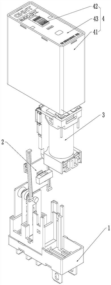
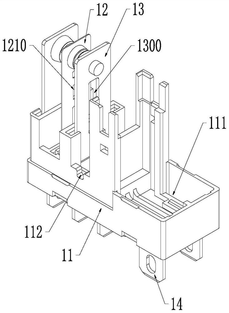
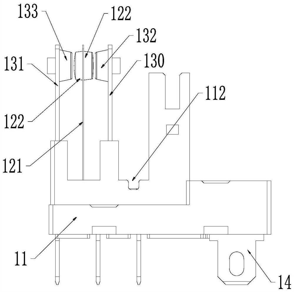
[0047] Such as figure 1 As shown, the electromagnetic relay of the present invention includes a base assembly 1 , a transmission member 2 , an electromagnetic system 3 and a cover assembly 4 . Such as figure 2 with image 3 As shown, the base assembly 1 of the present invention includes a base 11 , a moving reed assembly 12 installed on the base 11 , a static reed assembly 13 and a lead-out end 14 . An installation cavity 111 for installing the electromagnetic system 3 is provided on the top surface of one end of the base 11 , and a lead-out end 14 is connected to the bottom surface, and a moving reed assembly 12 and a static reed assembly 13 are installed on the other end of the base 11 ....


PUM


Abstract

An electromagnetic relay disclosed by the present invention comprises an electromagnetic system, a base assembly and a transmission member, a movable reed assembly of the base assembly is arranged corresponding to a normally closed contact and a normally open contact of a static reed assembly, an elastic member is connected between a yoke and the transmission member, an armature is connected with the transmission member, the transmission member is installed on a base, and the transmission member is installed on the base. The transmission part can swing or move relative to the base and comprises a push rod and a pull-back hook which are arranged corresponding to the movable contact spring assembly. When the electromagnetic system is positively electrified, the armature is driven to act to push the transmission piece, and the push rod pushes the movable contact spring assembly to close the normally open contact; the electromagnetic system is electrified reversely, the armature is driven to act reversely, the elastic piece recovers deformation, the transmission piece is pulled back together, and the pull-back hook pulls the movable contact spring assembly to close the normally-closed contact. According to the electromagnetic relay, the transmission part, the elastic part and the yoke are matched with one another, and the push rod and the pull-back hook of the transmission part are matched with the movable contact spring assembly, so that bidirectional transmission is realized, and the reliability of a product is improved.

Description

technical field [0001] The invention relates to the technical field of low-voltage electrical appliances, in particular to an electromagnetic relay. Background technique [0002] For the existing electromagnetic relays, in order to confirm the mechanical state of the relay contact action, the transmission indication function is added, and the action state of the contact is fed back through the structural parts and directly identified through the observation window on the top surface of the product, which is very beneficial for customers. Keep abreast of the overall working status of the system during maintenance or testing to reduce the probability of system errors. [0003] At present, most of the transmission indicating mechanisms on the market are assembled structures. The action indicating mechanism is connected with the transmission mechanism by using the principle of leverage. After the product coil is excited, the displacement of the transmission mechanism increases t...

Claims


Application Information

Patent Timeline
Patent Type & Authority Applications(China)
IPC IPC(8): H01H50/64H01H50/08
Inventor 王琦
Owner ZHEJIANG CHINT ELECTRIC CO LTD
Why Eureka
Try Eureka