A rail flaw detection signal generation and processing device

A signal generation and processing device technology, which is applied in the direction of processing detection response signals, measuring devices, instruments, etc., can solve the problems of misjudgment, damage detection accuracy and efficiency, etc., to reduce noise interference and improve damage recognition rate , the effect of reducing the misjudgment rate

Active Publication Date: 2022-05-06
ZHUZHOU TIMES ELECTRONICS TECH CO LTD
View PDF7 Cites 0 Cited by
  • Summary
  • Abstract
  • Description
  • Claims
  • Application Information

AI Technical Summary

Problems solved by technology

[0007] In view of this, the object of the present invention is to provide a rail flaw detection signal generation and processing device to solve the technical problems that the existing rail flaw detection signal generation and processing device may cause misjudgment due to noise, and the accuracy and efficiency of damage detection are not high.

Method used


Image

  • A rail flaw detection signal generation and processing device
  • A rail flaw detection signal generation and processing device
  • A rail flaw detection signal generation and processing device

Examples


Embodiment 1

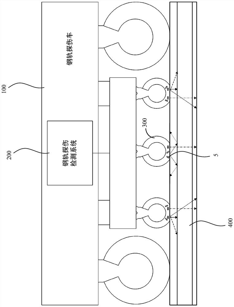
[0042] as attached Figure 5 As shown, an embodiment of a rail flaw detection signal generation and processing device specifically includes: a host computer parameter setting module 1, a real-time controller 2, a transmission pulse timing control module 3 and an ultrasonic excitation generation module 4. Set the pulse start time, transmission cycle and delay time of the high-voltage excitation signal of each channel through the host computer parameter setting module 1, and download them to the real-time controller 2. The real-time controller 2 generates corresponding control pulses through the bus control emission pulse sequence control module 3, and the control pulse controls the pulse number and the cycle of the ultrasonic excitation generation module 4 output high-voltage excitation signal, and the high-voltage excitation signal acts on the ultrasonic chip 5 (i.e. piezoelectric sensor) and generate an ultrasonic signal, which is incident on the rail 400. After the ultrason...

Embodiment 2

[0049] as attached Figure 9 As shown, an embodiment of a rail flaw detection signal generation and processing method based on the device described in Embodiment 1 specifically includes the following steps:

[0050] A) Set the pulse starting moment, the emission cycle and the delay time of the high-voltage excitation signal of each channel through the host computer parameter setting module 1, and download it to the real-time controller 2;

[0051] B) the real-time controller 2 generates corresponding control pulses through the bus control emission pulse sequence control module 3;

[0052] C) The emission pulse timing control module 3 controls the number and period of pulses of the high-voltage excitation signal output by the ultrasonic excitation generation module 4 by outputting control pulses;

[0053] D) The ultrasonic excitation generating module 4 outputs a high-voltage excitation signal to act on the ultrasonic chip 5 and generate an ultrasonic signal, which is incident...


PUM


Abstract

The invention discloses a rail flaw detection signal generation and processing device, comprising: a parameter setting module of a host computer, a real-time controller, a timing control module of emission pulses and an ultrasonic excitation generation module. Set the pulse start time, transmission cycle and delay time of the high-voltage excitation signal of each channel through the parameter setting module of the host computer, and download them to the real-time controller. The real-time controller controls the emission pulse timing control module to generate corresponding control pulses through the bus, and the control pulse controls the number and period of pulses and periods of the high-voltage excitation signal output by the ultrasonic excitation generation module. The high-voltage excitation signal acts on the ultrasonic chip and generates ultrasonic signals. The ultrasonic signal is incident on the rail. The invention can solve the technical problems that the existing rail flaw detection signal generation and processing device may cause misjudgment due to noise, and the accuracy and efficiency of damage detection are not high.

Description

technical field [0001] The invention relates to the technical field of ultrasonic non-destructive flaw detection, in particular to a rail flaw detection signal generation and processing device with marker signals, which can be applied to technical fields including rail flaw detection, ship flaw detection, aviation flaw detection and the like. Background technique [0002] Large-scale ultrasonic rail flaw detection vehicle is a common detection tool for detecting internal damage of rails. Based on the principle of ultrasonic reflection, the large-scale wheeled rail flaw detection vehicle uses high-voltage excitation pulses to excite the ultrasonic chip in the probe wheel 300, and the generated ultrasonic signal passes through the detection wheel fluid. , the wheel film, and the coupling liquid layer are incident to the rail 400, and the propagation paths of the ultrasonic chips at different angles in the rail are different. figure 1 shown. The ultrasonic signal propagates in...

Claims


Application Information

Patent Timeline
Patent Type & Authority Patents(China)
IPC IPC(8): G01N29/44G01N29/22G01N29/04
CPCG01N29/4454G01N29/22G01N29/04
Inventor 罗江平李红梁蔡培尧关伟赵志刚曹经纬夏浪王文星赵明明
Owner ZHUZHOU TIMES ELECTRONICS TECH CO LTD
Why Eureka
Try Eureka