Baffle type flood gate for transformer substation

A baffle type, substation technology, applied in distribution substations, substation/distribution device enclosures, substation/switch layout details, etc., can solve the problems of low utilization rate, no flood control effect, troublesome operation, etc. Convenience, good flood control effect, easy to operate effect

Pending Publication Date: 2022-04-12
STATE GRID HENAN ELECTRIC POWER COMPANY ANYANG POWER SUPPLY
View PDF0 Cites 0 Cited by
  • Summary
  • Abstract
  • Description
  • Claims
  • Application Information

AI Technical Summary

Problems solved by technology

[0002] In the current life, people are inseparable from electricity, and uninterruptible power supply has become an inevitable requirement. When extreme weather conditions such as heavy rain occur, it is particularly important to protect power supply facilities. If there is a large-scale power outage in extreme weather, it will cause incalculable The power supply facilities are usually very delicate, and it takes a certain amount of time and manpower to complete the repair after the damage
At present, the entrances and exits of traditional substation buildings are generally sliding doors, which have no flood control function. Therefore, substations have also become weak points and key points of attention against floods. It is too troublesome, time-consuming and labor-intensive, and cannot be efficiently dealt with in emergencies. The baffle walls used in the market are expensive and require some manpower to install on site in an emergency. The utilization rate is not high and it is easy to In the event of loss and failure, using a permanently sealed gate will cause inconvenience in entering and exiting the power station; therefore, it is very necessary to provide a substation baffle-type flood control door with a reasonable structure, good flood control effect, and easy operation

Method used


Image

  • Baffle type flood gate for transformer substation
  • Baffle type flood gate for transformer substation
  • Baffle type flood gate for transformer substation

Examples


Embodiment 1

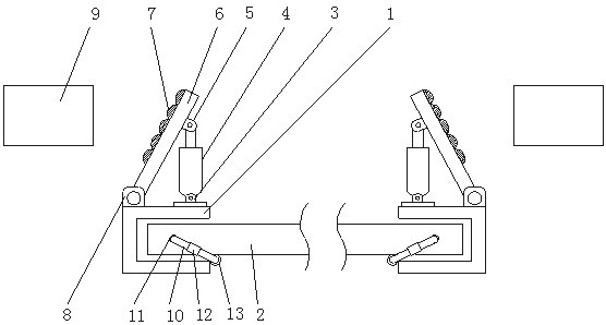
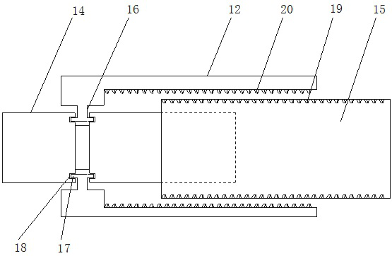
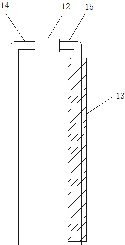
[0020] Such as Figure 1-5 As shown, the baffle type flood control door of the substation includes a U-shaped clamp 1, a water baffle 2 is arranged inside the U-shaped clamp 1, and a first hinge seat 3 is arranged behind the U-shaped clamp 1, so The first hinged seat 3 is fixedly provided with a hydraulic rod 4, the power end of the hydraulic rod 4 is connected with a second hinged seat 5, and the second hinged seat 5 is fixedly arranged on the side baffle 6, and the side baffle The outer surface of the plate 6 is fixedly provided with a sealing strip 7, and the side baffle 5 is connected to the rear of the U-shaped clamp 1 through the third hinge seat 8, and a plurality of water baffles 2 are arranged inside the U-shaped clamp 1. , the two ends of the water retaining plate 2 are provided with insertion holes 11, the insertion holes 11 are provided with a U-shaped fixed rod 10, and the U-shaped fixed rod 10 includes a fixed rod 14, a sliding rod 15 and an adjustment member 12,...

Embodiment 2

[0023] Such as Figure 1-5 As shown, the baffle type flood control door of the substation includes a U-shaped clamp 1, a water baffle 2 is arranged inside the U-shaped clamp 1, and a first hinge seat 3 is arranged behind the U-shaped clamp 1, so The first hinged seat 3 is fixedly provided with a hydraulic rod 4, the power end of the hydraulic rod 4 is connected with a second hinged seat 5, and the second hinged seat 5 is fixedly arranged on the side baffle 6, and the side baffle The outer surface of the plate 6 is fixedly provided with a sealing strip 7, and the side baffle 5 is connected to the rear of the U-shaped clamp 1 through the third hinge seat 8, and a plurality of water baffles 2 are arranged inside the U-shaped clamp 1. , the two ends of the water retaining plate 2 are provided with insertion holes 11, the insertion holes 11 are provided with a U-shaped fixed rod 10, and the U-shaped fixed rod 10 includes a fixed rod 14, a sliding rod 15 and an adjustment member 12,...


PUM


Abstract

A water baffle is arranged in a U-shaped clamping plate, a first hinge seat is arranged behind the U-shaped clamping plate, a hydraulic rod is fixedly arranged on the first hinge seat, the power end of the hydraulic rod is connected with a second hinge seat, the second hinge seat is fixedly arranged on a side baffle, and a sealing strip is fixedly arranged on the outer surface of the side baffle. The side baffle is connected with the rear portion of the U-shaped clamping plate through a third hinge seat, a plurality of water baffles are arranged in the U-shaped clamping plate, inserting holes are formed in the two ends of each water baffle, U-shaped fixing rods are arranged in the inserting holes, each U-shaped fixing rod comprises a fixing rod, a sliding rod and an adjusting piece, a connecting block is arranged on the rear side in the adjusting piece, and a protruding block is arranged on the connecting block. The protruding block is arranged in an annular groove, the annular groove is formed in a fixing rod, the top of the fixing rod is embedded in the sliding rod, and bottom sealant is arranged at the bottom of the U-shaped clamping plate. The flood control device has the advantages of being reasonable in structure, good in flood control effect and convenient to operate.

Description

technical field [0001] The invention relates to the technical field of substation flood control, in particular to a substation baffle type flood control door. Background technique [0002] In the current life, people are inseparable from electricity, and uninterruptible power supply has become an inevitable requirement. When extreme weather conditions such as heavy rain occur, it is particularly important to protect power supply facilities. If there is a large-scale power outage in extreme weather, it will cause incalculable The power supply facilities are usually very delicate, and it takes a certain amount of time and manpower to complete the repair after the damage. At present, the entrances and exits of traditional substation buildings are generally sliding doors, which have no flood control function. Therefore, substations have also become weak points and key points of attention against floods. It is too troublesome, time-consuming and labor-intensive, and cannot be ef...

Claims


Application Information

Patent Timeline
IPC IPC(8): H02B1/28H02B1/50H02B1/26H02B7/06
Inventor 张霄张占营席晟哲孙浩然冯晓兰赵悠悠赵新航胡明迪魏民郭鹏伟刘岩
Owner STATE GRID HENAN ELECTRIC POWER COMPANY ANYANG POWER SUPPLY
Why Eureka
Try Eureka