Eureka AIR delivers breakthrough ideas for toughest innovation challenges, trusted by R&D personnel around the world.

An external circulation cooling new energy motor

An external circulation cooling and new energy technology, applied in the direction of motors, cooling/ventilation devices, electric components, etc., can solve the problems of low integration of devices, bloated volume, poor heat dissipation efficiency, etc., to facilitate liquid circulation, cooling liquid Uniform distribution, improve the effect of heat dissipation

Active Publication Date: 2022-05-17
海门市华联机电有限公司
View PDF3 Cites 0 Cited by
  • Summary
  • Abstract
  • Description
  • Claims
  • Application Information

AI Technical Summary

Problems solved by technology

[0004] Most of the existing new energy motors use the shell to dissipate heat from the internal stator. The heat dissipation efficiency is poor, and the temperature of the motor is likely to be too high, resulting in damage and difficulty in use. Moreover, the existing motor uses an external liquid cooling device, and its volume Bloated, low degree of device integration

Method used


Image

  • An external circulation cooling new energy motor
  • An external circulation cooling new energy motor
  • An external circulation cooling new energy motor

Examples


Embodiment 1

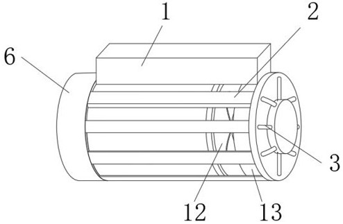
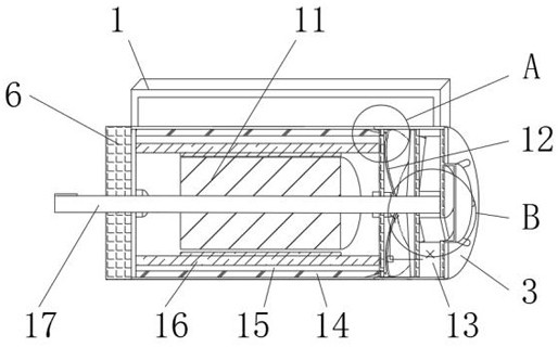
[0030] Such as Figure 1-4 As shown, an external circulation cooling type new energy motor includes a motor main body 6, a liquid storage tank 1 is provided on the top of the motor main body 6, and a heat dissipation mechanism 12 is provided at one end of the motor main body 6, and one side of the heat dissipation mechanism 12 is away from the motor main body 6. The side is connected with a drive mechanism 13, and the end of the drive mechanism 13 away from the heat dissipation mechanism 12 is connected with a drainage sealing plate 3. The surface of the motor body 6 is evenly embedded with a cooling grid 2, and the inside of the motor body 6 is fixedly connected with a stator 16. The motor body The inside of 6 is provided with a cooling chamber 14 for cooling the spoiler 15, the cooling chamber 14 communicates with the liquid storage bin 1, and the cooling grid 2 includes a cooling rod 7, a delivery pipe 8, a connecting rod 9 and a guide rod 10 , the cooling rod 7 is embedded...

Embodiment 2

[0033] On the basis of Example 1, as Figure 1-4 As shown, the conveying pipe 8 inside the heat dissipation rod 7 is arranged spirally against the inner wall of the heat dissipation chamber, and the middle part of the stator 16 drives the rotor 11 , and the middle part of the rotor 11 is provided with a drive shaft 17 .

[0034] When in use, the heat dissipation effect of the heat dissipation cavity on the delivery pipe 8 is effectively improved by spirally arranging the delivery pipe 8 inside the cooling rod 7 .

[0035] Such as Figure 1-6 As shown, the heat dissipation mechanism 12 includes a heat dissipation groove 18, a sealing plate 19 and a scroll blade 20, the sealing plate 19 is fixedly connected to the side end surface of the motor body 6, the heat dissipation groove 18 is opened at the end of the sealing plate 19 away from the motor body 6, and the scroll blade 20 is fixedly connected with the drive shaft 17, and the scroll blade 20 rotates coaxially with the drive...


PUM


Abstract

The invention discloses an external circulation cooling type new energy motor, which includes a motor body, a liquid storage tank is provided on the top of the motor body, a heat dissipation mechanism is provided at one end of the motor body, and a side of the heat dissipation mechanism is away from the motor body A drive mechanism is connected, and the end of the drive mechanism away from the heat dissipation mechanism is connected with a drainage sealing plate. The surface of the motor body is evenly embedded with a cooling grid, and the inside of the motor body is fixedly connected with a stator. There is a cooling chamber for cooling the spoiler inside, and the cooling chamber communicates with the liquid storage tank. The cooling grid includes cooling rods, delivery pipes, connecting rods and guide rods. The cooling rods are embedded On the surface of the main body of the motor, the connecting rod and the guide rod are fixedly connected with the cooling rod, the device can realize the circulation cooling of the motor, and the device is highly compact, and the integrated integration has high practicability.

Description

technical field [0001] The invention relates to the technical field of motor equipment, in particular to an external circulation cooling type new energy motor. Background technique [0002] A motor is a device that converts electrical energy into mechanical energy. It uses energized coils (that is, stator windings) to generate a rotating magnetic field and acts on the rotor (such as a squirrel-cage closed aluminum frame) to form a magneto-electric power rotation torque. [0003] Chinese Invention Patent Publication No. CN110165801A, the embodiment of the invention discloses a new energy motor, which is a two-in-one motor and generator. The motor can also generate electricity while working normally. The outer shell of this motor is the rotor, and the permanent magnet poles are fixed on the The inner side of the rotor is ring-shaped, and the two sides of the rotor are end covers. The end covers are fixed on the rotor, and the stator core is fixed on the shaft tube. There are ...

Claims


Application Information

Patent Timeline
Patent Type & Authority Patents(China)
IPC IPC(8): H02K9/19H02K9/06H02K5/20H02K5/18H02K5/06
CPCY02T10/64
Inventor 王武
Owner 海门市华联机电有限公司
Why Eureka
Eureka Blog
Learn More