Supercharge Your Innovation With Domain-Expert AI Agents!

Compensating for tracking inaccuracies

A compensation tracking and accurate technology, applied in the field of medical systems, can solve problems such as miscalculation of the spatial position of the tracked object and the impact of the overall result of the medical procedure

Pending Publication Date: 2022-04-12
BRAINLAB
View PDF0 Cites 0 Cited by
  • Summary
  • Abstract
  • Description
  • Claims
  • Application Information

AI Technical Summary

Problems solved by technology

Whereas errors during the initial object localization prior to the actual tracking process (e.g. poor marker detection) can have a severe impact on the overall outcome of the medical procedure and may eventually lead to miscalculation of the spatial position of the tracked object

Method used


Image

  • Compensating for tracking inaccuracies
  • Compensating for tracking inaccuracies
  • Compensating for tracking inaccuracies

Examples


Embodiment Construction

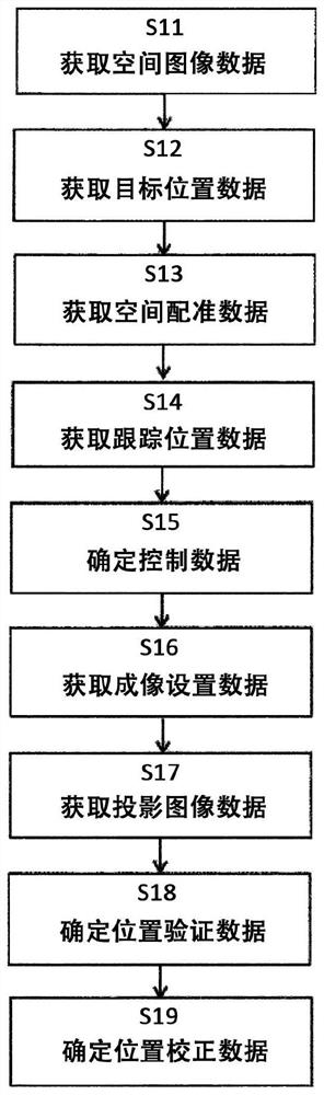
[0113] figure 1 Shown are the basic steps of the method according to the first aspect of the invention, which has been detailed above.

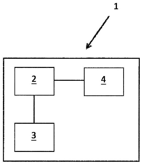
[0114] figure 2 A schematic diagram of a medical system 1 according to the fifth aspect is shown. The system is generally designated with reference numeral 1 and comprises a computer 2, an electronic data storage device 3 (such as a hard disk) for storing at least spatial image data, and a tracking system 4 (such as an optical IR tracking system). The components of the medical system 1 have the functions and characteristics described above.

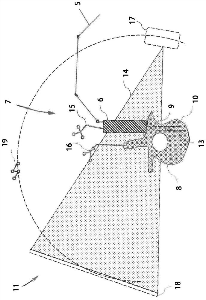
[0115] image 3 An exemplary positional setup of a projection imaging device 11 with an emitter 17 and a detector 18 that generates an x-ray image 12 of a vertebra 8 and an instrument 6 is shown (see Figure 4 ).

[0116] The imaging acquisition process described above provides a three-dimensional image data set of the vertebrae 8, such as a CT data set or an MR data set. The practitioner defines...


PUM


Abstract

A method of the present disclosure includes moving an object, such as a medical device or instrument, to a desired spatial position based on tracking data provided by a tracking system. Once it is determined from the tracking data that the object has reached the desired spatial position, a projection image is generated that is registered with the desired spatial position and displays the object. Based on the image data, it is possible to verify whether the object has actually reached the desired position, or whether the actual position of the object deviates from the desired position due to errors or inaccuracies, thereby taking measures to compensate for these errors or inaccuracies.

Description

technical field [0001] The invention relates to a computer-implemented method of compensating for tracking inaccuracies, a corresponding computer program, a computer-readable storage medium storing the program, a computer executing the program, and a medical system comprising an electronic data storage device and the computer. Background technique [0002] In computer-assisted surgery (CAS), radiosurgery and similar medical fields, the determination of the spatial orientation (spatial positioning and / or spatial orientation) of anatomical structures, equipment and instruments relative to each other is usually carried out by so-called tracking systems, such as optical tracking system, electromagnetic (EM) tracking system, or ultrasonic tracking system. This type of tracking system is adapted to identify tracking markers that are closely attached to the object, while the spatial position of these tracking markers is determined or tracked over time. Before the spatial position ...

Claims


Application Information

Patent Timeline
Patent Type & Authority Applications(China)
IPC IPC(8): A61B34/20
CPCG16H20/40G16H40/63A61B34/20A61B2034/2068A61B2034/2055A61B2090/376A61B2034/107A61B90/50A61B34/25A61B2034/2051A61B2034/2063A61B2034/2065G06T7/70A61B6/12A61B6/487G06T2207/10064G06T2207/10116
Inventor 约尔格·乌德曼弗雷德·韦瑟
Owner BRAINLAB
Features
  • R&D
  • Intellectual Property
  • Life Sciences
  • Materials
  • Tech Scout
  • Unparalleled Data Quality
  • Higher Quality Content
  • 60% Fewer Hallucinations
Learn More