
Anti-blocking gas-water separator capable of automatically dehydrating based on ship equipment

A gas-water separator and anti-clogging technology, which is applied in the direction of separation methods, dispersed particle separation, chemical instruments and methods, etc., can solve problems such as errors, poor separation effects, and inability to accurately control discharge volume, so as to improve separation effects and operate simple effect

Pending Publication Date: 2022-04-15
天长市蓝天船舶设备制造有限公司
View PDF0 Cites 0 Cited by
  • Summary
  • Abstract
  • Description
  • Claims
  • Application Information

AI Technical Summary

Problems solved by technology

[0005] The purpose of the present invention is to provide an anti-clogging gas-water separator based on marine equipment that can be automatically dehydrated to solve the problem in the prior art that is proposed in the above background technology. For the drainage system of the gas-water separator, when the bottom of the gas-water separator When the liquid rises to a certain height, it is necessary to discharge the accumulated liquid in time through electronic devices or manual control, but because electronic devices and manual drainage cannot accurately control the discharge volume each time, resulting in more or less errors, resulting in separation The problem of poor performance
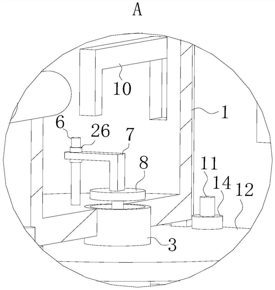
[0008] When working, in the prior art, for the drainage system of the gas-water separator, when the liquid at the bottom of the gas-water separator rises to a certain height, it is necessary to discharge the accumulated liquid in time through electronic devices or manual control, but due to electronic devices and Manual drainage cannot accurately control the discharge volume each time, resulting in more or less errors and poor separation effects. This technical solution can solve the above problems. The specific operation is as follows: first inject the liquid into the installation through the injection pipe In the box, the separation mechanism is used to separate. When the separated liquid falls to the bottom of the installation box, the separated water enters the drainage box through the first drain pipe, and the weight of the drainage box increases. Under the action of the elastic reset button , the drainage box drives the push rod to move downward until the U-shaped push frame pushes the L-shaped connecting frame, so that the L-shaped connecting frame drives the sealing block to move downward to seal the top of the first drain pipe. At this time, the bottom of the installation box is separated. The water cannot flow into the drainage tank, and the liquid level rises, and then the water flowing into the drainage tank is automatically discharged after the second drainage, and the weight of the drainage tank is reduced. Under the action of the elastic reset button, the drainage tank drives The rod rises again, and the U-shaped push frame cancels the contact with the L-shaped connecting frame until the push rod touches the bottom of the sealing block, pushes the sealing block upwards, opens the first drain pipe again, and water flows into the drainage tank again. The surface is lowered, and because the discharge speed of the first drain pipe and the second drain pipe is the same each time, the volume of water flowing into the drainage tank is equal each time, and the capacity of the water discharged each time is also the same, so the installation box will not be too much Discharge the liquid in the tank to avoid receiving too much liquid, causing the separated liquid to enter the drainage tank, causing waste and avoiding the error of more or less discharge, resulting in poor separation effect

Method used


Image

  • Anti-blocking gas-water separator capable of automatically dehydrating based on ship equipment
  • Anti-blocking gas-water separator capable of automatically dehydrating based on ship equipment
  • Anti-blocking gas-water separator capable of automatically dehydrating based on ship equipment

Examples


Embodiment Construction

[0027] The following will clearly and completely describe the technical solutions in the embodiments of the present invention with reference to the accompanying drawings in the embodiments of the present invention. Obviously, the described embodiments are only some, not all, embodiments of the present invention. Based on the embodiments of the present invention, all other embodiments obtained by persons of ordinary skill in the art without creative efforts fall within the protection scope of the present invention.

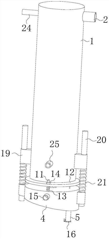
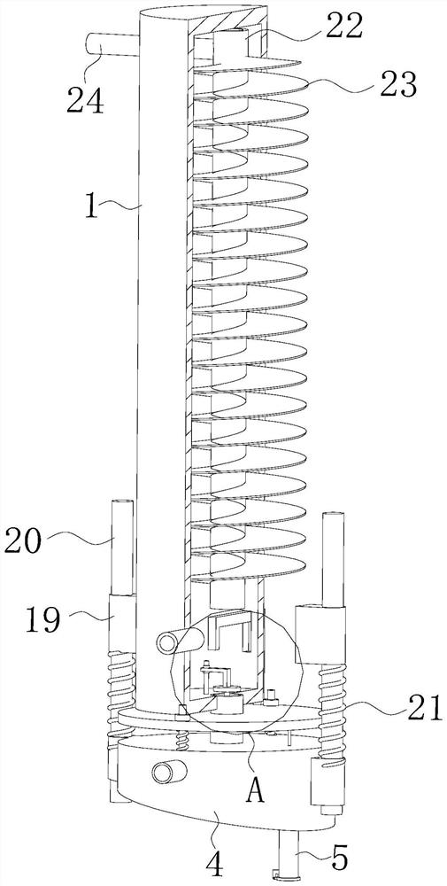
[0028] see Figure 1-5 , the present invention provides a technical solution: an anti-clogging gas-water separator based on marine equipment that can be automatically dehydrated, including an installation box 1, the outer wall of the top end of the installation box 1 is fixed and connected with a liquid injection pipe 2, and the inner wall of the installation box 1 is set There is a separation mechanism, and the bottom of the installation box 1 is provided with an ...


PUM


Abstract

The invention belongs to the field of gas-water separators, and discloses an anti-blocking gas-water separator capable of automatically dewatering based on ship equipment, which comprises a mounting box, a liquid injection pipe fixedly communicates with the outer side wall of the top end of the mounting box, a separation mechanism is arranged on the inner side wall of the mounting box, and an intermittent drainage mechanism is arranged at the bottom end of the mounting box. The intermittent drainage mechanism comprises a first drainage pipe, the top end of the first drainage pipe fixedly communicates with the bottom end of the mounting box, the bottom end of the first drainage pipe is slidably connected with a drainage box, and the bottom end of the drainage box fixedly communicates with a second drainage pipe. By arranging the intermittent drainage mechanism, the drainage box can intermittently receive and discharge liquid separated in the mounting box, meanwhile, it is guaranteed that the volumes of the liquid received and discharged each time are the same, the situation that too much liquid in the mounting box is discharged is avoided, and the situation that too much liquid is received, consequently, the separated liquid enters the drainage box, and waste is caused is avoided.

Description

technical field [0001] The invention discloses an anti-clogging gas-water separator based on ship equipment and capable of automatic dehydration in the field of gas-water separators. Background technique [0002] The gas-water separator is mainly used to separate gas and liquid in the liquid-containing system. It has the advantages of high water removal efficiency and small volume. , if it encounters an obstruction, the gas will deflect and go away, while the liquid will continue to have a forward speed due to inertia, and the forward liquid will adhere to the blocking wall and gather downward due to the action of gravity, and will be discharged through the discharge pipe. [0003] In the prior art, for the drainage system of the gas-water separator, when the liquid at the bottom of the gas-water separator rises to a certain height, it is necessary to discharge the accumulated liquid in time through electronic devices or manual control. The discharge volume cannot be precis...

Claims


Application Information

Patent Timeline
Patent Type & Authority Applications(China)
IPC IPC(8): B01D45/08
Inventor 李贻飞魏燕李训和
Owner 天长市蓝天船舶设备制造有限公司
Learn More