
Constant flow pump device

A technology of constant flow pump and plunger, which is applied to parts, pumps, and pump components of pumping devices for elastic fluids, and can solve problems such as huge experimental investment and cumbersome flow systems

Active Publication Date: 2018-02-09
CHINA PETROLEUM & CHEM CORP +1
View PDF5 Cites 0 Cited by
  • Summary
  • Abstract
  • Description
  • Claims
  • Application Information

AI Technical Summary

Problems solved by technology

If the double plunger one-way constant flow pump is used to pump alternately, a stable and constant flow can be achieved. However, in the dynamic constant pressure flow reaction system, there are often multiple independent liquid outlet channels that require constant flow. At this time, it must be arranged at each independent channel. A set of dual plunger constant flow pumps, resulting in a cumbersome flow system and a huge investment in experiments

Method used


Image

  • Constant flow pump device
  • Constant flow pump device

Examples


Embodiment Construction

[0022] The present invention will be further described below in conjunction with accompanying drawing.

[0023] The particulars presented here are exemplary and used for illustrative discussion of embodiments of the invention only, and are presented to provide what is believed to be the most useful and understandable description of the principles and conceptual aspects of the invention. Regarding this point, there is no attempt to introduce the structural details of the present invention beyond the level required for a basic understanding of the present invention. Those skilled in the art can clearly understand how to implement the present invention in practice through the description and accompanying drawings. Several forms.

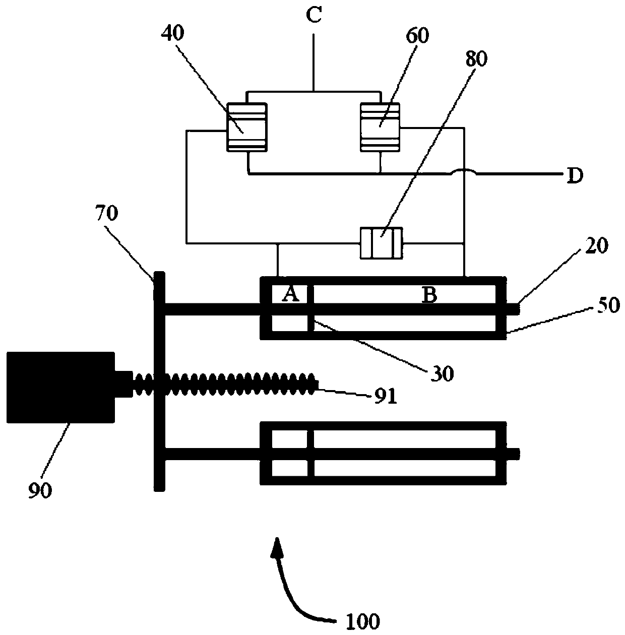
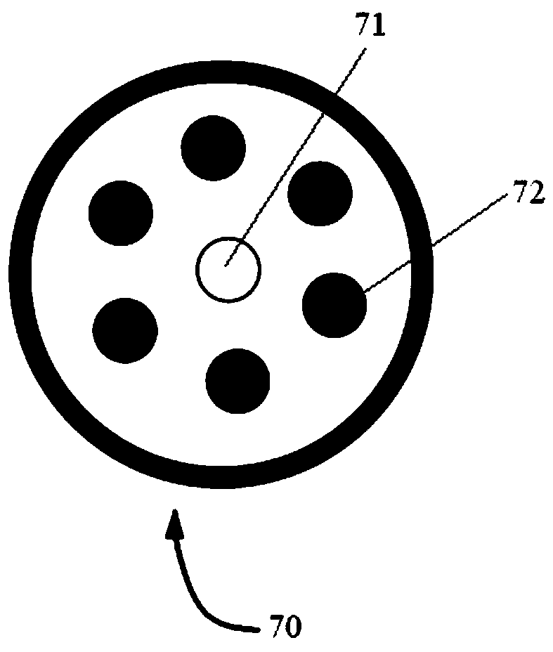
[0024] figure 1 is a schematic structural view of the constant flow pump 100 according to the present invention. The constant flow pump device 100 includes a plunger barrel 50, a plunger 30 reciprocating in the plunger barrel 50, the plunger 30 divide...


PUM


Abstract

The invention discloses a constant flow pump device, which comprises a plunger barrel, a plunger reciprocating in the plunger barrel, the plunger divides the plunger barrel into a sealed first chamber and a second chamber, and respectively The first reversing valve and the second reversing valve connected to the first chamber and the second chamber. Wherein, after the first reversing valve and the second reversing valve are connected in parallel, one end communicates with the external liquid inlet, and the other end communicates with the external liquid outlet. The invention can realize bidirectional continuous constant current, and can also realize bidirectional continuous constant current for multiple channels in a dynamic constant pressure flow system.

Description

technical field [0001] The invention belongs to the field of mechanical power and relates to a constant flow pump device. Background technique [0002] The constant flow pump device is a commonly used mechanical device in the liquid material conveying system, and different systems have different requirements for the constant flow pump device. The existing constant flow pump plunger cylinders are all one-way half-cycle constant flow, that is, constant flow when the plunger advances at a constant speed, and when the plunger is pushed to the limit, the constant flow stops, and the plunger needs to retreat to the starting position before restarting the constant flow. flow. At the same time, in order to realize continuous constant flow, the existing constant flow pump uses two plungers to alternately perform unidirectional constant flow operation. [0003] In the dynamic constant pressure flow reaction system, fresh liquid is continuously input. In order to keep the pressure in...

Claims


Application Information

Patent Timeline
Patent Type & Authority Patents(China)
IPC IPC(8): F04B17/03F04B53/10
Inventor 刘伟新俞凌杰范明张文涛徐二社陈红宇鲍芳
Owner CHINA PETROLEUM & CHEM CORP
Learn More