Clothes airing device for smart home
A smart home and installation tube technology, which is applied in the direction of household clothes dryers, washing devices, household appliances, etc., can solve the problems of no light-gathering effect, adjustment, and low drying efficiency, and achieve a wide range of use, high efficiency, Effect of improving drying efficiency
- Summary
- Abstract
- Description
- Claims
- Application Information
AI Technical Summary
Problems solved by technology
Method used
Image

Examples
Embodiment 1
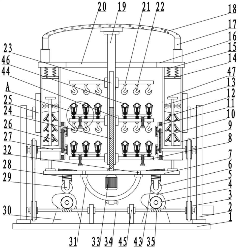
[0027] see Figure 1-4 , a clothes drying device for smart home use, comprising a bottom plate 1, and further comprising:
[0028] The installation rods 2 fixedly arranged on both sides of the bottom plate 1, one side of the installation rod 2 is fixedly connected to the fixed plate 25, one side of the fixed plate 25 is fixedly provided with the installation cylinder 9, and the top of the installation cylinder 9 is fixedly connected to the top plate 16;
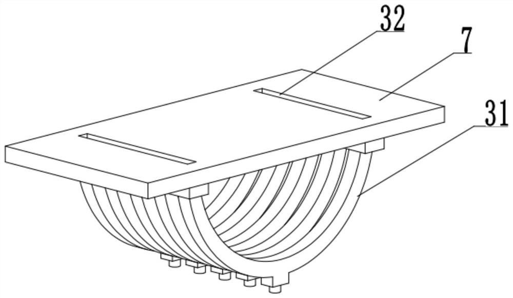
[0029] The clothes-drying mechanism 44 arranged between the installation tubes 9 includes a bearing plate 7, on which the threaded column 24 is rotated and connected, and the bottom of the bearing plate 7 on the axial side of the threaded column 24 is fixedly connected to the drive motor 33, and the drive motor 33 The output shaft is fixedly connected to one end of the threaded column 24. A bearing cylinder 19 is arranged above the threaded column 24. A threaded groove 23 is provided in the bearing cylinder 19. The threaded c...
Embodiment 2
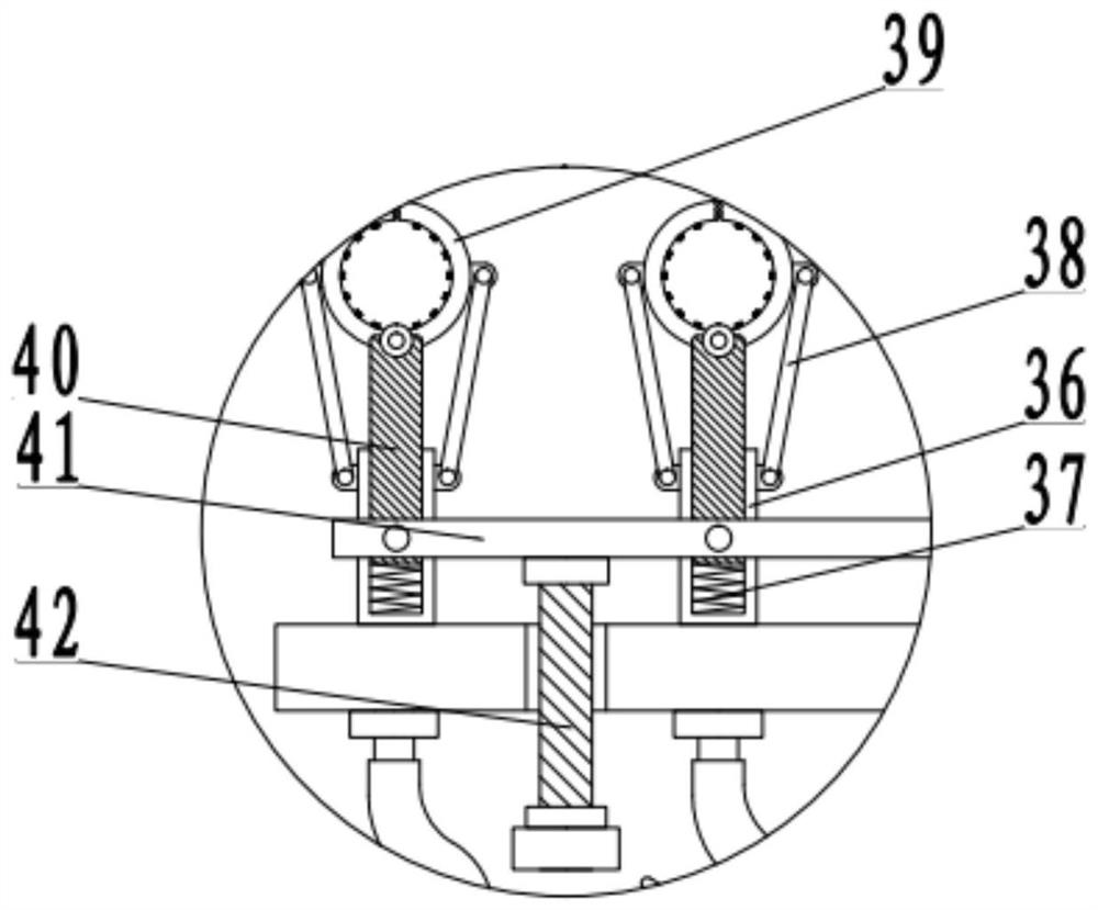
[0032] see Figure 1-4 , the other content of this embodiment is the same as that of Embodiment 1, the difference is that the clothes hanging assembly 46 includes an installation motor 21, the installation motor 21 is fixedly connected with the fixed rod 8, and the bottom of the output shaft of the installation motor 21 is fixedly connected The hook 22, the fixed rod 8 below the hook 22 is fixedly connected to the limit cylinder 36, the inner bottom of the limit cylinder 36 is fixedly connected to the support member 37, the top of the support member 37 is fixedly connected to the piston rod 40, and the two sides of the top of the piston rod 40 are rotationally connected and clamped. Rod 39 , the transmission arm 38 is hinged between the clamping rod 39 and the side wall of the limiting cylinder 36 .
[0033] One side of the piston rod 40 is fixedly connected to the linkage arm 41, and the fixed rod 8 on the side of the linkage arm 41 is threaded to set an adjustment column 42,...
PUM
 Abstract
Description
Claims
Application Information
 - Generate Ideas
- Intellectual Property
- Life Sciences
- Materials
- Tech Scout
- Unparalleled Data Quality
- Higher Quality Content
- 60% Fewer Hallucinations
Browse by: Latest US Patents, China's latest patents, Technical Efficacy Thesaurus, Application Domain, Technology Topic, Popular Technical Reports.
© 2025 PatSnap. All rights reserved.Legal|Privacy policy|Modern Slavery Act Transparency Statement|Sitemap|About US| Contact US: help@patsnap.com