[0041] In order to make the objects, technical solutions, and advantages of the present invention more clear, the technical solutions in the embodiments are clear and complete, and the following examples are intended to illustrate the invention. However, it is not intended to limit the scope of the invention.
[0042] In the description of the present invention, it is to be noted that the terms "upper", "lower", "front", "post", "left", "right", "vertical", "inside", "outside", etc. The orientation or positional relationship indicated is based on the orientation or positional relationship shown in the drawings, is meant to facilitate the description of the present invention and simplified description, rather than indicating or implying that the device or component must have a specific orientation. Construct and operation, so it is not understood to be the limitation of the invention.
[0043] In the description of the invention, it is to be noted that the term "mount", "connected", "connection", such as a fixed connection, unless otherwise expressly specified and defined, unless otherwise expressly specified and defined. Connect, or integrate; it can be mechanical connection, or an electrical connection; may be directly connected, or indirectly over the intermediate medium. The specific meaning of the above terms in the present invention will be appreciated to those skilled in the art.
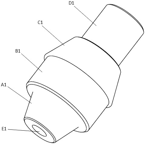
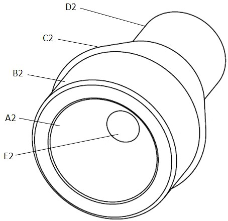
[0044] Such as figure 1 , figure 2As shown, a male female step axis, including the male-mounted shaft and the mother pin; the common-welded axis is connected by the connecting surface IA1, the bearing surface IB1, the limit surface IC1 and the clamp ID1 to constitute a stepped axis, and the ladder The center of the shaft is provided with through holes II 1 through which the step IIA2, the carrier surface IIB2, the limit surface IIC2 and the clamping handle IId2 are sequentially connected to constitute a step axis, and the center of the step axis is provided with Through the through hole IIE2 of the step axis; wherein the male distribution shaft is paired with the mother pin, the connecting surface Ia1 is combined with the connecting surface IIa2, and the through hole IE1 is coaxial with the through hole IIE2, which will carry the radial force of the carrier Partially converted into axial force to achieve mutual locking.
[0045] Further Solution: The connection surface IA1 is a conical boss, the connecting surface IIA2 is a cone pit, and the cone boss is inserted into the conical pit, and the tapered surface of the two can be bonded; the bearing surface IB1 and the bearing surface IIB2 are cylindrical The outer diameter is equal to the diameter; the limit surface IC1 and the limit surface IIC2 are conical bosses, both size specifications; clamping handles Id and clamping handle IId2 are cylindrical, both size specifications; through-hole IE1 The inner diameter of the through hole IIE2 is the same.
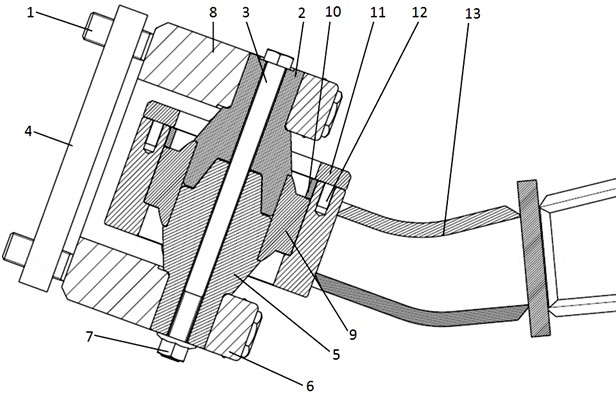
[0046] Such as image 3 As shown, a biaxially hinge connection means including a fixed assembly, a movable component, a ball hinge assembly, and a fastening attachment; the fixing assembly includes the public shaft 5, the mother pin 2, through the bolt 3, fastening nut 7, The bearing pressure plate 6, the pressure plate 8, the screw plate 4; the movable assembly 13 is a moving structure such as a suspension, the hinge assembly is a three-way bearing such as a joint bearing 9 or a rubber bearing; the fastening accessory includes a spacer 10, a cover 11, Screw 12.
[0047] The specific connection scheme is: the movable assembly 13 reserved a step mounting seat hole, the joint bearing 9 is mounted in the mounting inner hole, by the spacer 10 in the attachment, the cover 11 axially position, a set of screws 12 is tight Solid, axial direction of the outer ring of the joint bearing 9 is pressed in the inner hole of the movable assembly 13.
[0048] Continue reference image 3 As shown, the male distribution shaft 5 and the mother pin shaft 2 are separated from the inner ring of the joint bearing 9, respectively; the carrier surface IB1 of the male distribution shaft 5 is the same as the outer diameter dimension of the carrier surface IIb2 of the mother pin 2, respectively. The inner hole of the joint bearing 9 is fitted, and the radial force received by the joint bearing 9 is reliably transmitted.
[0049] Continue reference image 3 As shown, the limit surface IC1 of the male distribution shaft 5 and the limit surface IIC2 of the mother pin shaft 2 is a symmetric cone boss feature, and the large cone terminals are fitted to the inner ring end surface of the joint bearing 9, axially positioned. Reliable transmission of the sections 9 received the radial force; the cone boss is well avoided, the stress concentration caused by the cross-sectional mutation of the mother pin; the male shaft 5 and the mother pin shaft 2 coaxially in the assembly state.
[0050] Continue reference image 3 As shown, through the axial direction of the bolt 3 throughout the public, the through hole II1 and through hole IIE2 of the mother pin shaft, the fastening nut 7 is locked, so that the connecting surface IA1 of the male and mother pin is completely attached to the connection surface IIA2 The mutual preload can not only be reliably fastened to the inner ring of the joint bearing 9, but also becomes a generic force, but also carries the radial force of the portion of the joint surface Ia1 and the connecting surface IIa2.
[0051] The pressing plate 6 is paired with the pressure plate 8 as a pairing, and the clamping handle Id and the clamping handle IId2 of the male, mother pin is pressed against the semi-circular cylindrical groove D4 reserved in the pressure plate 8, respectively, to ensure the public, mother. The pin is connected to the pressure plate 8.
[0052] Such as Figure 4 As shown, the bearing pressure plate 6 is presented with a semicircular cylindrical groove D3 that matches the outer diameter of the clamping handle Id and the clamping handle IId2 of the male, mother pin; the bearing pressure plate 6 is half circular cylindrical groove D3 near-pin shaft The mounting end is opened with a chamfer F1 to ensure the axial pressure plate 6 is fitted with the male, mother pin transition end surface, and axially restricted; the height of the semi-circular cylindrical groove D3 and the clamping handle Id 1 and clips of the mother pin Handle IID2 is equivalent.
[0053] The bearing pressure plate 6 is known as the center axis of the semi-circular cylindrical groove D3, and two through holes A3 are opened, facilitating the bolt 1 through the fastening.
[0054] Such as Figure 5 As shown: The pressure plate holder 8 is respectively symmetrical, the central hollow, the central axis, and the central axis, the central axis, two semi-circular cylindrical grooves that match the outer diameter of the clamping handle Id and the clamping handle IId2 of the mount IId2. D4; Semi-circular cylindrical groove D4 near-pin shaft mounting end is opened with chamfer F2; the pressure plate 8 is processed in the semi-circular cylindrical groove D4 near the central hollow end processing has a semi-circular dispersion G1, two semi-circular dispensers G1 Coax; Ensure that the pressure plate 8 is bonded to the male, mother pin transition end face, and axially, the pressure plate 8 is aligned with the center axis of the semi-circular cylindrical groove D4 is a reference symmetry, two pairs of through holes A4 arranged. It is convenient for the bolt 1 through the fastening; the height of the semi-circular cylindrical groove D4 and the clamping handle Id and the clamping handle IId2, the clamping handle Id and the clamping handle IId2.
[0055] It should be noted that the pressure plate 8 must be permanently fixed by welding and other means with the frame and other chassis structure components, ensuring the joint bearing 9 inner ring, the public distribution shaft 5, the mother pin 2, the pressure plate 8 and the frame and other chassis The structural components are reliably transmitted interaction.
[0056] After the pressure plate holder 8 and the bearing plate 6 are mounted and mounted, the through hole A3 reserved through the four bolts 1 through the bearing plate 6 and the pressure plate 8, and the through hole A4 is fastened, and the two-piece plate 4 is fastened, and the bearing pressure plate 6 , The male distribution shaft 5, the mother pin shaft 2 and the pressure plate 8 are reliable.
[0057] The threaded plate 4 is a strip, the symmetry is opened with a pair of threaded holes H1, the screw plate 4 is mounted vertically vertically, and the two threaded holes H1 of the screw plate 4 simultaneously and respectively fasten through the upper and lower two bearing plates. 6 bolts can effectively prevent the loose.
[0058] In summary, the fixing manner of the present invention effectively improves the disassembly and packaging of moving structural members compared to the existing traditional hinge means, enhances the repeated utilization of the articulated fastener, and improve the system maintenance.
[0059] In the specification provided here, a large number of specific details are explained. However, it will be appreciated that embodiments of the present invention can be practiced without these specific details. In some examples, well-known methods, structures, and techniques are not shown in detail so that it is not blurred to understand the specification.
[0060] Furthermore, those skilled in the art will appreciate that although some of the embodiments described herein include certain features included in other embodiments rather than other features, the combination of features of different embodiments also means in the present invention. The scope is within the protection range and different embodiments are formed. For example, in the above embodiment, those skilled in the art can be used in combination based on the technical solutions to be solved in the art, in accordance with the technical solutions to which the present application will solve.
[0061] The above is only a preferred embodiment of the present invention, and the present invention is not intended to be in any form, although the present invention has been disclosed in the preferred embodiment, but is not intended to limit the invention, any technique that is familiar with this patent The personnel do not depart from the technical solution of the present invention, as an equivalent embodiment of the present invention can be made by the technical content of the present invention, it is in accordance with the present invention. The technical substance is still within the scope of the present invention.