
A cryogenic ball valve and method of using the same

A technology of cryogenic and ball valves, applied in control valves, valve devices, valve details, etc., can solve problems such as easy leakage, large shrinkage, and valve rupture, and achieve simple structural design, uniform contact stress, and improved sealing. Effect

Active Publication Date: 2022-08-05
CHENGDU CHENGGAO VALVE +1
View PDF10 Cites 0 Cited by
  • Summary
  • Abstract
  • Description
  • Claims
  • Application Information

AI Technical Summary

Problems solved by technology

[0003] Existing ball valves will have a large hole in the valve body, resulting in uneven structure of the valve body, not a regular geometry, and high requirements for the dimensional accuracy, roughness, and roundness of the sealing surface
At the same time, when the temperature difference in the environment where the ball valve is located is large or when the low-temperature medium is transported, the valve body is cooled and causes a large amount of shrinkage, and due to the uneven structure or thickness of the valve body, the sealing surface of the valve body will produce serious irregular distortion, which will eventually lead to Seal failure of the valve body and seat assembly, prone to leakage
At the same time, the existing ball valves cannot be dynamically adjusted for different environmental temperature differences or the sealing pretightening force of the transport medium, and the valve adaptability is low
[0004] Secondly, the existing ball valve usually has a spring between the bonnet and the ball, resulting in a large local stress on the lower part of the ball and the lower part of the valve seat, uneven force on the entire ring of the valve seat, and uneven wear on the upper and lower ends of the valve seat. , after the valve is opened and closed for a certain period of time, the wear of the valve seat at 6 o'clock is more severe than that at 12 o'clock
When the elastic force provided by the spring on the ball is not enough to compensate for the uneven wear of the valve seat, the valve seat is prone to leakage
[0005] Furthermore, the pressure relief methods of existing ball valves usually have the following two methods: 1. By opening small pressure relief holes on the ball, the valve can only achieve one-way sealing, and the valve does not have two-way sealing; Pressure relief on the back of the seal, this pressure relief method is very unreliable, and it cannot be released to the designated end at the designated pressure. When the transport medium has a high expansion ratio, if the valve cavity cannot be released in time, the valve may be at risk of rupture

Method used


Image

  • A cryogenic ball valve and method of using the same
  • A cryogenic ball valve and method of using the same
  • A cryogenic ball valve and method of using the same

Examples


Embodiment 1

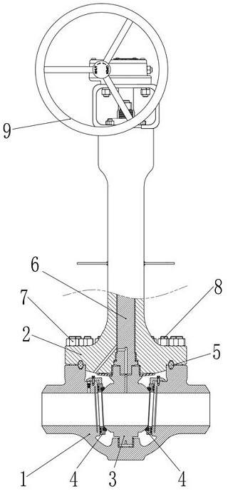
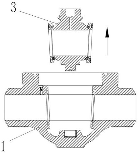
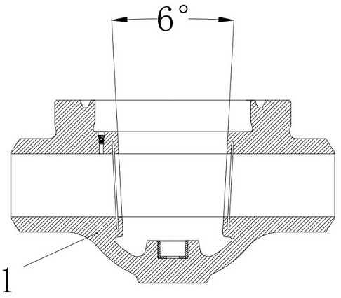
[0046] as attached figure 1 -Attached Figure 7 As shown, the present invention provides a cryogenic ball valve, which includes: a valve body 1, a valve cover 2, a ball body 3, and a valve seat assembly 4; wherein, the upper end of the valve body 1 is provided with an opening and a mounting surface, The mounting surface and the lower flange of the valve cover 2 are connected by bolts 8 and nuts 7; the ball 3 and the valve seat assembly 4 are installed into the valve body 1 from the opening, and the two symmetrically arranged valve seat assemblies 4 are connected to the valve body on both sides respectively. The sealing surface on 1 and the ball body 3 are in sealing contact; the valve cover 2 is provided with a valve stem 6, and the upper side of the valve cover 2 is provided with a manual operator 9, which is connected with the ball body 3 through the valve stem 6. 3. A first boss is arranged on the upper side, and a disc spring 10 is arranged between the ball 3 and the valv...

Embodiment 2

[0050] Preferably, on the basis of Embodiment 1, Embodiment 2 is provided with a damping check valve 12 on the second boss, the damping check valve 12 includes a check valve body, and the check valve body is provided with a spherical valve core and a first A coil spring 12.1, one end of the first coil spring 12.1 is against the check valve body, and the other end is against the spherical valve core. The damping check valve 12 adjusts the valve central chamber 40 to the valve central chamber 40 according to the pressure value of the valve central chamber 40. The upstream valve chamber 20 or the downstream valve chamber 30 is selectively communicated or closed. to attach Image 6 As shown in the example, the damping check valve 12 has only one-way flow capacity, that is, the medium can only flow from the valve middle cavity 40 to the upstream valve cavity 20 , and cannot flow from the upstream valve cavity 20 to the valve middle cavity 40 . By adjusting the pre-tightening force...

Embodiment 3

[0053] In order to further improve the sealing performance of the cryogenic ball valve of the present invention, Embodiment 3 makes the following optimizations on the basis of Embodiments 1 and 2. as attached Image 6 -Attached Figure 8 As shown in , the cryogenic ball valve of the present invention is also provided with a first elastic ring groove 13 and a second elastic ring groove 14 at the second bosses of the upstream valve cavity 20 and the downstream valve cavity 30 of the valve body 1, respectively. The elastic ring groove 13 and the second elastic ring groove 14 are substantially parallel to the sealing surface; wherein the ratio of the groove width d of the first elastic ring groove 13 and the second elastic ring groove 14 to the distance D from the sealing surface is 0.4-0.5, Preferably it is 0.4; the ratio of the groove depth h of the first elastic ring groove 13 and the second elastic ring groove 14 to the thickness H of the second boss is 0.5-0.6, preferably 0....


PUM


Abstract

The invention relates to a cryogenic ball valve and a method for using the same. The cryogenic ball valve comprises a valve body, a valve cover, a ball body and a valve seat assembly; the ball body and the valve seat assembly are loaded into the valve body from an opening, and two valve seat assemblies are symmetrically arranged The two sides are respectively in sealing contact with the sealing surface on the valve body and the ball; the cryogenic ball valve is provided with a disc spring and an elastic block, which provide downward force and act on the ball and the valve seat respectively. On the assembly, the valve seat assembly and the ball body, the valve seat assembly and the valve body are tightly attached together, so as to achieve the sealing effect.

Description

technical field [0001] The invention belongs to the field of fluid control valves, and in particular relates to a cryogenic ball valve and a method for using the same. low temperature medium. Background technique [0002] In my country, ball valves are widely used in petroleum refining, long-distance pipelines, chemical and other industries. The ball valve is mainly used to cut off, distribute and change the flow direction of the medium in the pipeline. It can be closed tightly by rotating 90 degrees and a small torque. Generally, ball valves are suitable for switching and shut-off valves, so they need to have good sealing performance. [0003] The existing ball valve will open a large hole on the valve body, resulting in an uneven structure of the valve body, which is not a regular geometric body, and requires high dimensional accuracy, roughness and roundness of the sealing surface. At the same time, when the ambient temperature difference of the ball valve is large or ...

Claims


Application Information

Patent Timeline
Patent Type & Authority Patents(China)
IPC IPC(8): F16K5/06F16K5/08F16K5/20F16K15/18F16K27/06F16K27/08
CPCF16K5/0689F16K5/08F16K5/201F16K27/067F16K27/08
Inventor 傅建川白开玉曾品其曾和友张明
Owner CHENGDU CHENGGAO VALVE
Learn More