High-speed rail bearing with high speed, heavy load and low friction

A low-friction, bearing technology, applied in the field of high-speed rail bearings, can solve the problems of bearing friction resistance and friction wear increase, raceway indentation, cage cracking, etc., and achieve the effect of reliable lubrication conditions, large bearing capacity and stable operation

Pending Publication Date: 2020-07-31
孟萍
View PDF0 Cites 0 Cited by
  • Summary
  • Abstract
  • Description
  • Claims
  • Application Information

AI Technical Summary

Problems solved by technology

[0003] (1) Stress concentration: The stress concentration at the end of the tapered roller bearing roller is an irreversible congenital fatal defect, and its common main hazard is to cause raceway indentation and peeling;
[0004] (2) The rollers are easy to skew: The biggest congenital fatal flaw of tapered roller bearings is that the uneven force on the contact line of the rollers during rotation can easily make the rollers skew. The mechanical concept of roller skew is: the rollers are skewed When the rolling surface is no longer in linear contact with the raceway, it is tightly stuck between the raceways of the inner and outer rings at a certain angle like a wedge, and slides and rubs against the inner and outer rings, causing the rolling body One end is indented or peeled off, and the other end is severely worn, which directly causes ring raceway indentation, peeling, cage cracking or rib cracking, which often occurs in wheel bearings of heavy-duty vehicles. The method of sub-convexity reduces the stress concentration of the roller end, but still cannot change the mechanical nature of the stress concentration, nor can it fundamentally correct the defects of its congenital mechanical structure;
[0009] Because the mechanical principle of the combined load of the tapered roller bearing is realized by the size of the roller contact angle (inclination angle), the tapered roller bearing directly distributes the received load on both the radial and axial sides of the bearing according to the size of the contact angle. One direction, that is: directly derive a constant axial force, and lead to serious congenital defects, that is: the load on the bearing cannot automatically adjust the optimal ratio of the combined load with different working conditions, so that the axial and radial directions of the bearing are always In the set force state, the axial force caused by the contact angle is the same as the principle of the lateral adjustment nozzle of the rocket jet engine. What a danger it will be! ?
[0010] The same principle

Method used


Image

  • High-speed rail bearing with high speed, heavy load and low friction
  • High-speed rail bearing with high speed, heavy load and low friction
  • High-speed rail bearing with high speed, heavy load and low friction

Examples


Embodiment 1

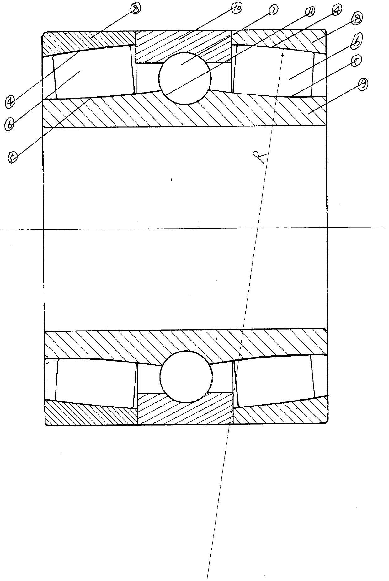
[0071] Such as figure 1 A high-speed heavy-duty low-friction high-speed rail bearing shown includes an outer ring 1, an inner ring 2 of a deep groove ball bearing, two double-half inner rings 3, a row of spherical rolling elements 7 and two rows of spherical rollers 6 , the inner circumference of the outer ring 1 is provided with a shared spherical roller track 4, the radius of curvature of the shared spherical roller track 4 is greater than the radius of the bearing roller circumferential track, so that the shared spherical roller track 4 set on the inner circumference of the bearing outer ring 1 The axial section has an olive-shaped elliptical ball bladder roller track structure, and a deep groove ball rolling body track 11 is provided in the middle of the inner circumference of the outer ring 1 sharing the axial distance of the spherical roller track 4,

[0072] The inner ring 2 of the deep groove ball bearing is arranged in the middle of the inner circumference of the oute...

Embodiment 2

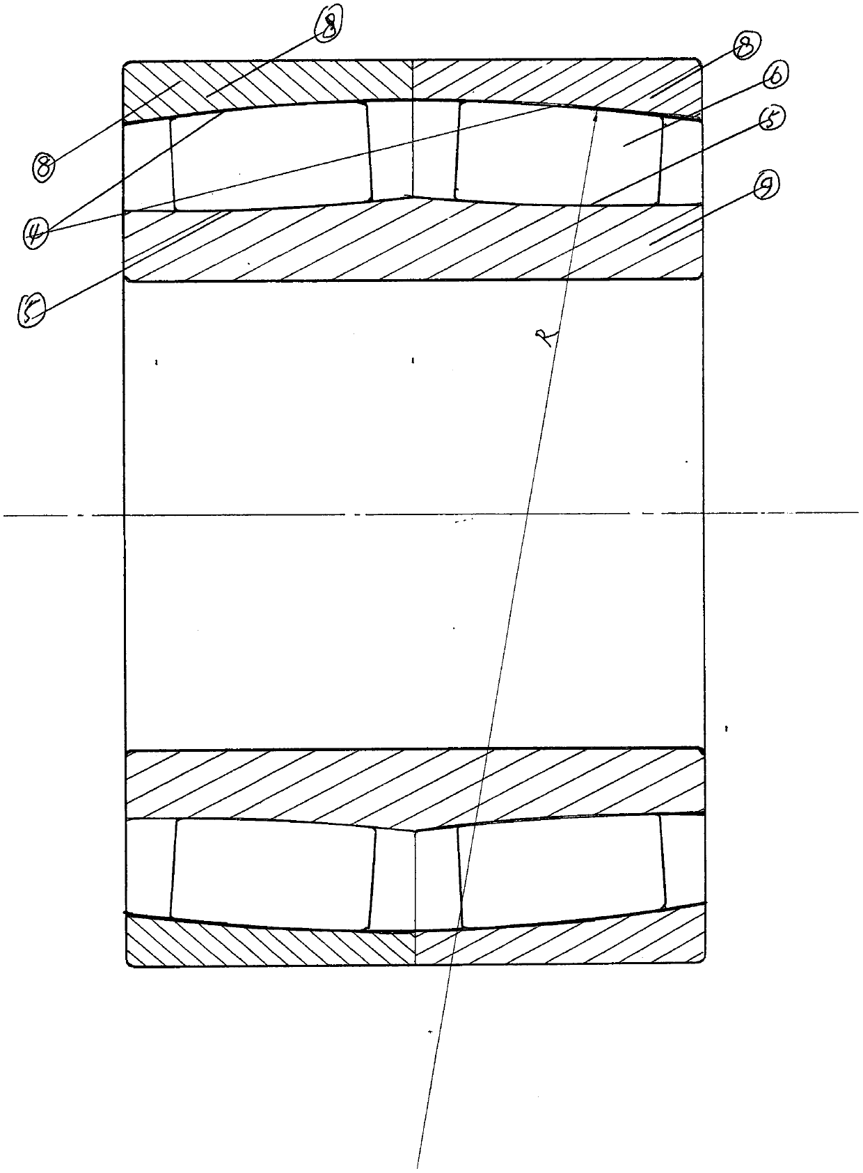
[0075] Such as figure 2 The high-speed heavy-duty low-friction high-speed rail bearing shown includes two double-half outer rings 8, an inner ring 9 and two rows of spherical rollers 6, and the inner circumferences of the two double-half outer rings 8 are respectively provided with spherical rollers. The sub-track, after the two double-half outer rings 8 are concentrically combined, the inner circumference forms a shared spherical roller track 4, and the radius of curvature of the shared spherical roller track 4 is greater than the radius of the bearing roller circumferential track, so that the shared spherical roller track The axial section of the roller track 4 has an olive-shaped elliptical bladder structure,

[0076] Two rows of spherical roller tracks 5 are arranged at an axial distance from the outer circumference of the inner ring 9. The two rows of spherical roller tracks 5 form an angle of 5 degrees with the vertical axis of the bearing, and each of the two rows of s...

Embodiment 3

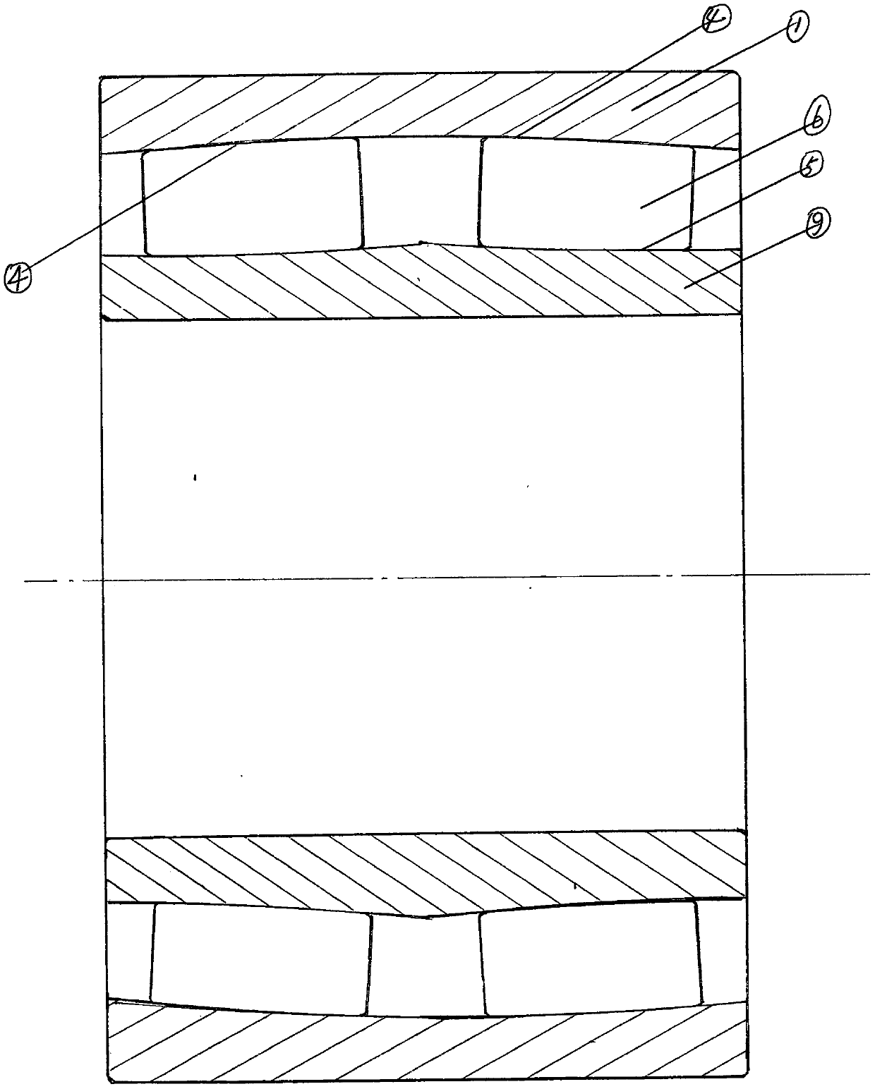
[0078] Such as image 3 A high-speed heavy-duty low-friction high-speed iron bearing shown includes an outer ring 1, an inner ring 9 and two rows of spherical rollers 6,

[0079] A shared spherical roller track 4 is arranged on the inner circumference of the outer ring 1, and the radius of curvature of the shared spherical roller track 4 is larger than the radius of the bearing roller circumferential track, so that the axial section of the shared spherical roller track 4 is an olive-shaped ellipse bile structure,

[0080] The outer circumference of the inner ring 9 is spaced apart from two spherical roller tracks 5, the two rows of spherical roller tracks 5 form an angle of 5 degrees with the vertical axis of the bearing, and each of the two spherical roller tracks 5 is provided with a row of spherical rollers. 6, the inner ring 9 is combined with the shared spherical roller track 4 provided on the inner circumference of the outer ring 1 through two rows of spherical rollers ...


PUM


Abstract

The invention relates to a bearing, in particular to a high-speed rail bearing with high speed, heavy load and low friction. The high-speed rail bearing with high speed, heavy load and low friction isformed by an outer sleeve ring, a deep groove ball bearing inner sleeve ring, two double half inner sleeve rings and three rows of rolling elements. A circle of deep groove ball rolling element railis arranged in the middle of an inner circle of the outer ring; a ball rolling element is arranged in the rail; a circle of spherical roller rail is arranged on each of two ends of the deep groove ball rolling element rail; spherical rollers are arranged in the spherical roller rails; the deep groove ball bearing inner sleeve ring is arranged in the middle of the inner circumference of the outer sleeve ring; through the combination of the ball rolling element and the deep groove ball rolling element rail arranged in the middle of the outer sleeve ring, a middle ball structure of a ball bearingis formed; reverse spherical roller rails are arranged on the outer circumferences of the two double half inner sleeve rings and are arranged on two sides of the deep groove ball bearing inner sleevering; and through the combination of the spherical rollers and a spherical roller rail arranged on the inner circumference of the outer sleeve ring, a reverse spherical roller bearing structure is formed. According to the high-speed rail bearing with high speed, heavy load and low friction provided by the invention, a combined load is borne by utilizing the advantage of two-point contact pure rolling friction of the ball rolling element, so that the rotation speed and the rotation accuracy of the bearing are improved; and the curvature radius of each roller rail is enlarged through each reverse spherical roller rail, so that a contact angle of the rollers is reduced, and the aims of high speed, heavy load, low friction and low temperature rise are achieved.

Description

technical field [0001] The invention relates to high-speed rail bearings. Background technique [0002] 1. At present: the high-speed rail bearings manufactured by developed countries in the world are still tapered roller bearings manufactured on the basis of advanced bearing materials and technology. Research data show that there are many fatal defects in the mechanical structure of tapered roller bearings, such as: [0003] (1) Stress concentration: The stress concentration at the end of the tapered roller bearing roller is an irreversible congenital fatal defect, and its common main hazard is to cause raceway indentation and peeling; [0004] (2) The rollers are easy to skew: The biggest congenital fatal flaw of tapered roller bearings is that the uneven force on the contact line of the rollers during rotation can easily make the rollers skew. The mechanical concept of roller skew is: the rollers are skewed When the rolling surface is no longer in linear contact with the...

Claims


Application Information

Patent Timeline
IPC IPC(8): F16C19/16F16C33/58F16C33/32
CPCF16C19/16F16C33/32F16C33/58Y02T10/86
Inventor 孟萍
Owner 孟萍
Why Eureka
Try Eureka