Sum-difference beam sparse array synthesis method for broadband wide-angle beam scanning

A technology of beam scanning and synthesis method, which is applied in the field of sum-difference beam sparse array synthesis of wide-bandwidth angular beam scanning, can solve problems such as not having wide-band and wide-angle beam scanning performance, and achieve the goal of reducing computational complexity and meeting application requirements Effect

Active Publication Date: 2022-04-15
UNIV OF ELECTRONICS SCI & TECH OF CHINA
View PDF3 Cites 2 Cited by
  • Summary
  • Abstract
  • Description
  • Claims
  • Application Information

AI Technical Summary

Problems solved by technology

However, the sum and difference beam synthesized by this method still does not have the performance of broadband and wide-angle beam scanning

Method used


Image

  • Sum-difference beam sparse array synthesis method for broadband wide-angle beam scanning
  • Sum-difference beam sparse array synthesis method for broadband wide-angle beam scanning
  • Sum-difference beam sparse array synthesis method for broadband wide-angle beam scanning

Examples


Embodiment Construction

[0047] In order to make the objects, technical solutions, and advantages of the present invention, the present invention will be further described in detail below with reference to the accompanying drawings.

[0048] The present invention is further explained in conjunction with one example. Design goal: The frequency range is between 1 GHz ~ 3GHz, and the beam scan is [45 °, 135 °], and the peak level of the firing / sub-valve region remains unchanged and the differenceable beam is ragged.

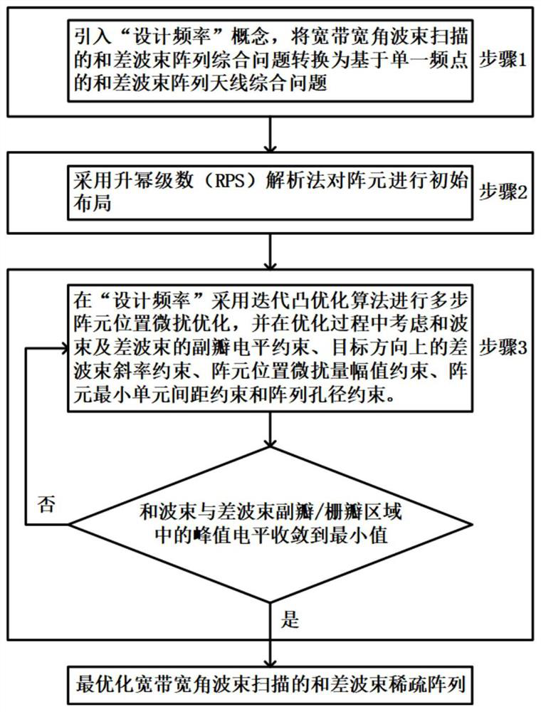
[0049] Implement the following steps:

[0050] Step 1: Due to F L = 1GHz and f H = 3GHz, using broadband ratio R f = F H / f L = 3 Measure the ratio of the highest frequency and the lowest frequency of the operating frequency section; due to beam pointing angles θ 0 ∈ [π / 2-θ max , π / 2 + θ max ], Θ max = 45 ° and u ∈ [-1- | sin θ max |, 1 + | sin θ max |], Using beam scanning distance ratio R u = Max {u} / max {u 0 } = (1+ | sinθ max |) = 1.707 Measure the increment of visible space after ...


PUM


Abstract

The invention provides a sum-difference beam sparse array synthesis method for broadband wide-angle beam scanning, and relates to array antenna pattern synthesis and antenna array element position optimization. The method comprises the following steps: step 1, introducing a concept of'design frequency ', and converting a sum-difference beam array synthesis problem of broadband wide-angle beam scanning into a sum-difference beam array synthesis problem based on a single frequency point; step 2, carrying out initial layout on the array elements by adopting a power series increasing (RPS) analysis method; and step 3, performing multi-step array element position perturbation optimization at the'design frequency 'by adopting an iterative convex optimization method, and setting a plurality of constraint conditions in the optimization process, such as a sidelobe level constraint of a sum beam and a difference beam, a difference beam slope constraint in a target direction, an array element position perturbation quantity amplitude constraint, an array element minimum spacing constraint and the like. According to the method, the sum beam and the difference beam with the broadband wide-angle beam scanning performance can be generated at the same time by optimizing the array element layout, and a plurality of constraint conditions are set to meet actual application requirements.

Description

Technical field [0001] The present invention relates to an antenna, and more particularly to a broadband width angle beam scan for a comprehensive method of a beam sparse array. Background technique [0002] And the difference beam array antenna has an important role in the radar and communication systems, and there is an important role in the accurate tracking and detection of the target, and therefore has caused extensive attention. There are many studies on the comprehensive problem of the array of difference beams. Most methods are to optimize the incentive distribution or the low sub-valve radial performance of the beam and the difference beam, or simplify the design complexity of beamforming network by optimizing the excitation distribution or the low sub-valve radial performance of beams and difference beams. Documents 1 and Documents 2 use Dolph ChebyShev and BayLiss power to synthesize and differentially integrated and differential beams, but the feed network design of t...

Claims


Application Information

Patent Timeline
Patent Type & Authority Applications(China)
IPC IPC(8): G06F30/20H01Q21/00G06F111/04
CPCG06F30/20H01Q21/00G06F2111/04Y02D30/70
Inventor 刘颜回刘泱陈礼阳杨仕文胡俊聂在平
Owner UNIV OF ELECTRONICS SCI & TECH OF CHINA
Why Eureka
Try Eureka