Protective cover mechanism and large-amount cash deposit machine thereof

A protective cover and deposit machine technology, which is applied to deposits in ATMs, parts of ATMs, computer parts, etc., can solve the development obstacles of unmanned banks, cannot be unattended, and increase labor costs and other problems, to achieve the effect of convenient replacement, prevention of banknote loss, and convenient storage

Pending Publication Date: 2022-04-15
WEIRONG TECH CO LTD
View PDF0 Cites 0 Cited by
  • Summary
  • Abstract
  • Description
  • Claims
  • Application Information

AI Technical Summary

Problems solved by technology

[0002] Self-service deposit machines are already very mature equipment, but the current self-service deposit machines can only deposit a small amount of cash, and manual counter operations are required for large amounts of cash, which obviously increases labor costs, and cannot be unattended, 24 hours Hourly on duty, causing technical obstacles for the subsequent development of unmanned banks
For large deposits, it is very important to select broken coins, counterfeit banknotes, and unrecognizable banknotes. The current self-service deposit machines are not perfect in this aspect, and some users need to verify the authenticity and deposit them as a whole after sorting them out. Current subsidized deposit machines do not have this feature

Method used


Image

  • Protective cover mechanism and large-amount cash deposit machine thereof
  • Protective cover mechanism and large-amount cash deposit machine thereof
  • Protective cover mechanism and large-amount cash deposit machine thereof

Examples


Embodiment Construction

[0038] The following will clearly and completely describe the technical solutions in the embodiments of the present invention with reference to the drawings in the embodiments of the present invention.

[0039] In describing the present invention, it should be understood that the terms "upper", "lower", "front", "rear", "left", "right", "top", "bottom", "inner", " The orientation or positional relationship indicated by "outside", etc. is based on the orientation or positional relationship shown in the drawings, and is only for the convenience of describing the present invention and simplifying the description, rather than indicating or implying that the referred device or element must have a specific orientation, so as to Specific orientation configurations and operations, therefore, are not to be construed as limitations on the invention.

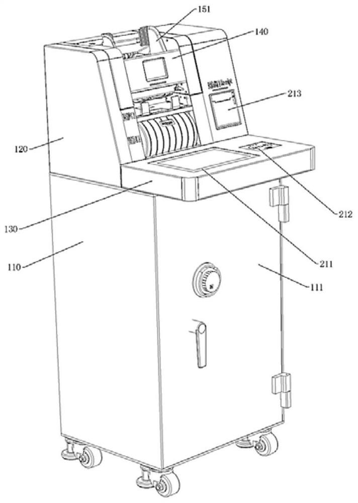
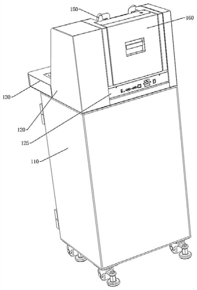
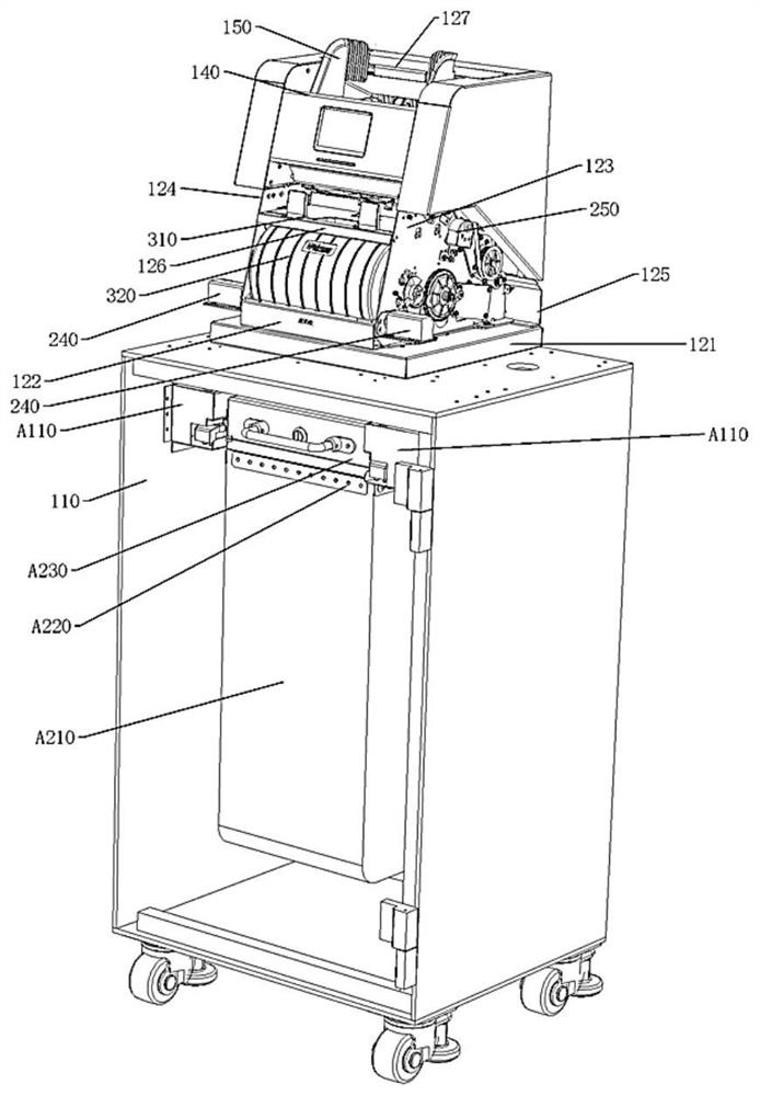
[0040] see Figure 1-Figure 29 , a large-amount deposit machine, including a safe 110, the safe 110 is hollow inside and has an opening ...


PUM


Abstract

The invention discloses a protective cover mechanism and a large-amount cash deposit machine thereof. The protective cover mechanism comprises a protective cover, and the protective cover is opened and closed through rotation to shield a cash receiving table and open the cash receiving table; the two sides of the protection cover are hinged to a first sorting side plate of the sorting module and a second sorting side plate of the sorting module through protection cover shafts respectively, one protection cover shaft penetrates through the first sorting baffle to be fixedly assembled with the induction plate, the protection cover shafts are fixedly assembled with the protection cover, a first power rod is installed on one side of the induction plate, and a second power rod is installed on the other side of the induction plate. The first power rod is provided with a first rod sliding groove, the first rod sliding groove and the second power pin are clamped and assembled in a sliding mode, the second power pin is installed on the second power rod, the second power rod is provided with a second rod sliding groove, and the end, away from the second power pin, of the second power rod is hinged to the first sorting baffle through a rod rotating shaft. The second rod sliding groove and a third power pin are clamped and assembled in a sliding mode, the third power pin is eccentrically installed on a power disc, and the power disc is installed on a motor shaft of a protection cover motor.

Description

technical field [0001] The invention relates to financial equipment, in particular to a protective cover mechanism and a large-value deposit machine thereof. Background technique [0002] Self-service deposit machines are already very mature equipment, but the current self-service deposit machines can only deposit a small amount of cash, and manual counter operations are required for large amounts of cash, which obviously increases labor costs, and cannot be unattended, 24 hours Hours of duty have created technical obstacles for the subsequent development of unmanned banks. For large deposits, it is very important to select broken coins, counterfeit banknotes, and unrecognizable banknotes. The current self-service deposit machines are not perfect in this aspect, and some users need to verify the authenticity and deposit them as a whole after sorting them out. Current subsidized deposit machines do not have this feature. [0003] To this end, the applicant designed a large-...

Claims


Application Information

Patent Timeline
Patent Type & Authority Applications(China)
IPC IPC(8): G07D11/125G07D11/14G07D11/16G07D11/165G07D11/18G07D11/23G07D11/50G07F19/00G07D7/04G07D7/20
CPCG07D11/125G07D11/165G07D11/14G07D11/16G07D11/18G07D11/50G07D11/23G07D7/20G07D7/04G07F19/202
Inventor 魏芳馨蔡耀准方镇唐逢飞黄威魏小兰王茂兴黎荣海
Owner WEIRONG TECH CO LTD
Why Eureka
Try Eureka