Acupuncture point electrical stimulation device for psychiatry department and use method
A psychiatric and electrical stimulation technology, applied in the directions of electrotherapy, physiotherapy positioning, and current-using instruments, etc., can solve the patient's back electric shock treatment, insufficient back fitting effect, and affect the treatment effect, etc., to achieve comfort. Improve, increase the effect of electric shock, improve the effect of treatment
- Summary
- Abstract
- Description
- Claims
- Application Information
AI Technical Summary
Problems solved by technology
Method used
Image
Examples
Embodiment 1
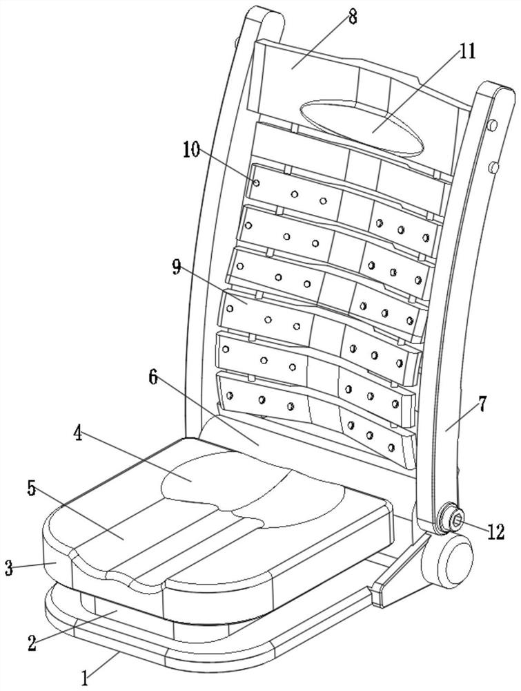
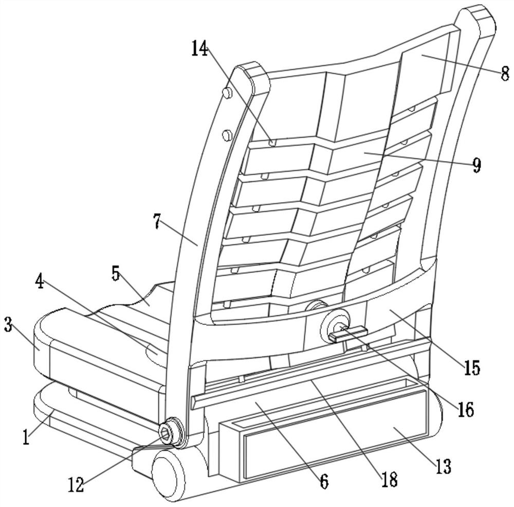
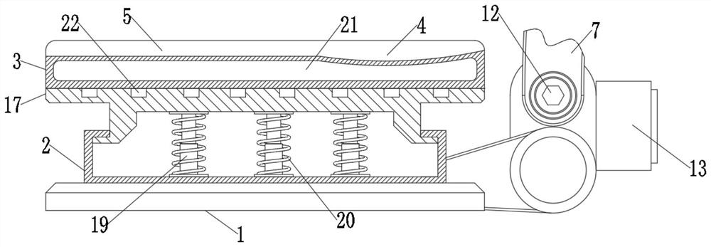
[0034] Electrostimulation therapy devices are usually simple wearable electric shock devices, which are less comfortable to use and are likely to affect the use of patients. Please refer to Figure 1-6 , this embodiment discloses a psychiatric acupoint electrical stimulation device, comprising a base 1 and a rotating connection box 6 on one side of the base 1, a backrest frame 7 is installed on both sides of the rotating connection box 6, and a Soft rubber cushion 3, the upper surface of soft rubber cushion 3 is provided with leg pit 5, the upper surface of soft rubber cushion 3 is also provided with buttock pit 4, the both sides of rotating connection box 6 and backrest frame 7 pass through fixed axle pin 12 is fixed, and the backrest frame 7 is equipped with a head backing plate 8, and the lower end of the head backing plate 8 is equipped with a combination frame 9, and the combination frame 9 is symmetrically provided with connecting hole grooves 24 on both sides, and the in...
Embodiment 2
[0037] In practical applications, the connection effect between the connecting frame 27 and the connecting hole groove 24 is not strong enough, and it is difficult to support the combined frame 9 to fit the patient's back. This embodiment is an improvement made on the basis of Embodiment 1. Specifically, please refer to Figure 1-6 One side of the connecting hole groove 24 is provided with a plug-in positioning hole 25, and the other side of the connecting hole groove 24 is provided with a mounting positioning hole 30, and the two ends of the connecting frame 27 are symmetrically installed with a rotating shaft outer ring 28, and the rotating shaft outer ring 28 is used to be stuck in the insertion positioning hole 25 and the installation positioning hole 30.
[0038] By first inserting one end of the rotating shaft outer ring 28 into the insertion positioning hole 25 and the inside of the installation positioning hole 30, and in this way, the two combined frames 9 are connect...
Embodiment 3
[0040] In practical applications, in order to prevent the outer ring 28 of the rotating shaft from falling off, the inside of the installation positioning hole 30 lacks a limit structure, which may easily cause it to fall off the inside of the installation positioning hole 30. This embodiment is an improvement made on the basis of Embodiment 2 , specifically, see Figure 1-6 A shrapnel 29 is installed inside the installation positioning hole 30 , and one end of the shrapnel 29 is connected to the inner wall of the installation positioning hole 30 .
[0041] Through the elastic effect of the shrapnel 29, when the outer ring 28 of the rotating shaft passes through the shrapnel 29, a driving force needs to be applied, so that the outer ring 28 of the rotating shaft presses the shrapnel 29 down, and the outer ring 28 of the rotating shaft can be snapped into the inside of the installation positioning hole 30 to complete For the limiting effect of the outer ring 28 of the rotating ...
PUM
 Abstract
Description
Claims
Application Information
 - R&D
- Intellectual Property
- Life Sciences
- Materials
- Tech Scout
- Unparalleled Data Quality
- Higher Quality Content
- 60% Fewer Hallucinations
Browse by: Latest US Patents, China's latest patents, Technical Efficacy Thesaurus, Application Domain, Technology Topic, Popular Technical Reports.
© 2025 PatSnap. All rights reserved.Legal|Privacy policy|Modern Slavery Act Transparency Statement|Sitemap|About US| Contact US: help@patsnap.com


